Cockpit floor for aircraft

a technology for aircraft cockpits and cockpits, applied in aircrafts, fuselages, transportation and packaging, etc., can solve the problems of difficult practice, large disadvantages, and long time-consuming for fuselage boxes to be assembled, and achieve high mechanical performan

Active Publication Date: 2009-01-13
AIRBUS OPERATIONS (SAS)
View PDF11 Cites 25 Cited by
  • Summary
  • Abstract
  • Description
  • Claims
  • Application Information

AI Technical Summary

Benefits of technology

[0014]Advantageously, the floor rods according to the invention designed to resist forces applied along the longitudinal direction can be easily and quickly assembled on the aircraft fuselage, simply by assembling them with their forward end being articulated to this fuselage. The fact that the forward end is assembled fixed to a longitudinal wall of the fuselage fixed to fuselage frames and preferably to an outer skin of this fuselage, makes it possible to distribute the forces very uniformly.
[0018]Consequently, such a cockpit floor has the advantage that rods can be included to resist longitudinal forces, such that the length of these rods is significantly less than the length of rods in the direction facing outwards from the centre of the floor and in the aft direction, due to the narrowing observed towards the forward part in this cockpit part of the aircraft. Thus, the reduction in the length of the rods would significantly reduce buckling problems during compression phases of these rods that occur in the case of an aircraft crash.
[0022]In other words, the fitting is fixed jointly to the main structure and to the upper skin assembled on top of the main structure, such that the forces passing through the rod can be simultaneously transmitted to these two elements, and then propagate through these elements. It is also clear that connecting the rod to the upper skin enables better distribution of the transmitted forces.

Problems solved by technology

This type of force may also be encountered during aircraft pressurisation phases causing a pressure increase in the cockpit.
In this type of embodiment according to prior art, a major disadvantage was detected due to the use of boxes to resist forces applied along the longitudinal direction of the aircraft.
The assembly of boxes on the fuselage frames take a long time and is difficult in practise since it may be necessary to successively disassemble and reassemble the bottom and top skins of these boxes.

Method used


Image

  • Cockpit floor for aircraft
  • Cockpit floor for aircraft
  • Cockpit floor for aircraft

Examples


Embodiment Construction

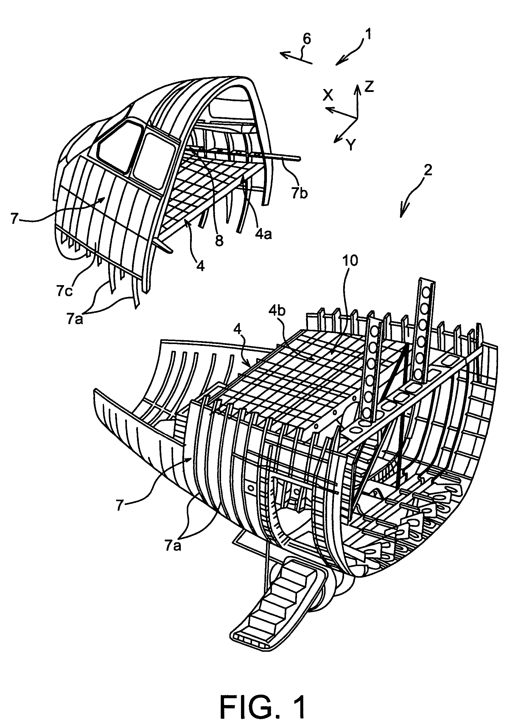
[0040]FIG. 1 shows a partial view of the forward part of an aircraft 1, and more precisely the nose part 2 of this aircraft, comprising a cockpit floor 4 according to a preferred embodiment of this invention.

[0041]Throughout the description given below, by convention X denotes the longitudinal direction of the aircraft 1, Y denotes the aircraft transverse direction, and Z denotes the vertical direction, these three directions being orthogonal to each other.

[0042]Furthermore, the terms > and > should be considered with respect to the direction of movement of the aircraft as a result of the thrust applied by the aircraft engines, this direction being shown diagrammatically by the arrow 6.

[0043]As can be seen in FIG. 1, the cockpit floor 4 extends in an XY plane over almost the entire length of the nose part 2 of the aircraft, and is installed on a fuselage 7 of the aircraft. As will be explained in detail later, the cockpit floor 4 is firstly installed on part of the longitudinal wall...


PUM


Abstract

The invention relates to an cockpit floor (4) for an aircraft comprising a plurality of spars (14) extending along a longitudinal direction (X) of the aircraft and a plurality of cross-beams (16) assembled to said spars (14) and running along a transverse direction (Y) of the aircraft, the spars (14) and the cross-beams (16) forming a primary structure (12) of the floor (14), the floor also comprising attachment means (64) used to assemble it to the aircraft fuselage. According to the invention, the attachment means comprise a plurality of rods (68) resisting forces applied along the longitudinal (X), each of the rods (68) having an aft end connected to the main structure and a forward end that will be connected to said fuselage, such that each rod is oriented such that its distance from the centre of the floor increases towards the forward end.

Description

TECHNICAL FIELD[0001]This invention relates in general to an aircraft cockpit floor comprising particularly a plurality of spars assembled to a plurality of cross-beams.STATE OF PRIOR ART[0002]The shape of an aircraft cockpit floor is adapted to the narrowing of the fuselage that occurs in this part of the aircraft, in a known manner, in the sense that its width reduces towards the forward part of the aircraft.[0003]Furthermore, this type of floor can extend towards the aft part as far as a cabin part of the aircraft, and more generally forms the floor of the entire nose part of the aircraft.[0004]This type of floor is then designed to satisfy several specific needs, for example such as the need for openings for integration of rudder bars and the cockpit central console, so that aircraft occupants can move about, various equipment such as electrical elements or seats can be installed, to resist mechanical forces that occur in the case of an aircraft crash, or to electromagnetically ...

Claims


Application Information

Patent Timeline
Patent Type & Authority Patents(United States)
IPC IPC(8): B64C1/18B64C1/00
CPCB64C1/18
Inventor VETILLARD, ALBANPARRO, EMMANUEL
Owner AIRBUS OPERATIONS (SAS)
Why Eureka
Try Eureka