Method of calculating the required lens power for an opthalmic implant

a technology of opthalmic implants and lens power, applied in the field of ophthalmic lenses, can solve the problems of uncompensated cylindrical refractive error, corneal astigmatism, and procedure itself can induce corneal astigmatism, and achieve the effect of reducing the risk of corneal astigmatism

Active Publication Date: 2009-01-13
ALCON INC
View PDF19 Cites 39 Cited by
  • Summary
  • Abstract
  • Description
  • Claims
  • Application Information

AI Technical Summary

Benefits of technology

[0010]Still another objective of the present invention is to provide a more accurate method of calculating the required post-operative refractive power of the implant.

Problems solved by technology

The cornea and crystalline lens also may be non-spherical and regular but asymmetric or toric, resulting in an uncompensated cylindrical refractive error referred to as corneal and lenticular astigmatisms, which in combination give ocular astigmatism.
Finally, if a surgical procedure is performed on the eye, the procedure itself can induce corneal astigmatism.
Thus, misalignment of the axis of cylinder of the implant with that of the cornea / eye is detrimental to the overall goal of optimum retinal image formation.
This method, however, does not use power vector analysis to determine the correct power or orientation of a toric implant.
They, however, failed to provide a direct guidance for surgeons in terms of how to do surgery correctly to optimal refractive outcomes.
In addition, these models do not account for the location of the lens within the eye.

Method used


Image

  • Method of calculating the required lens power for an opthalmic implant
  • Method of calculating the required lens power for an opthalmic implant
  • Method of calculating the required lens power for an opthalmic implant

Examples


Embodiment Construction

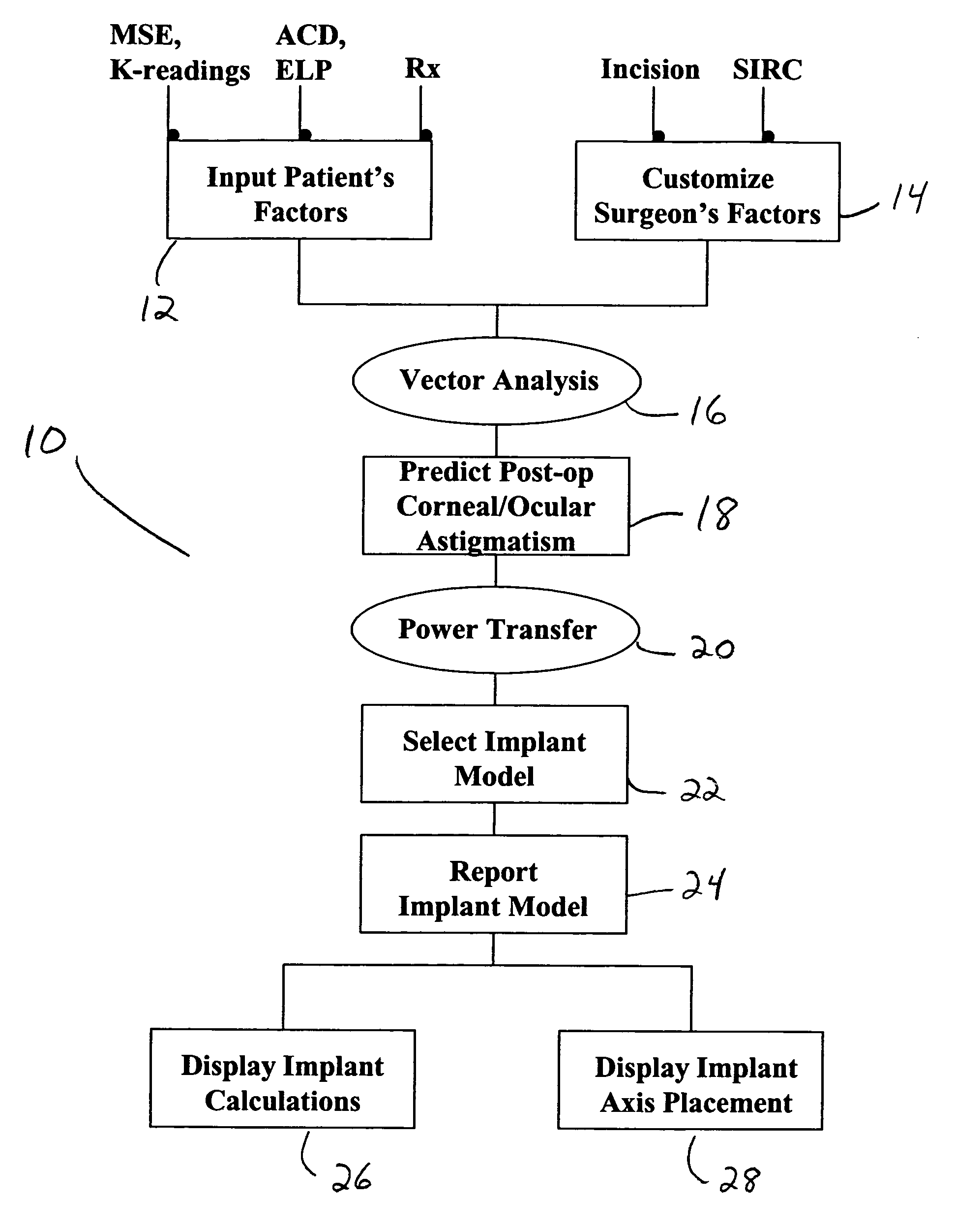
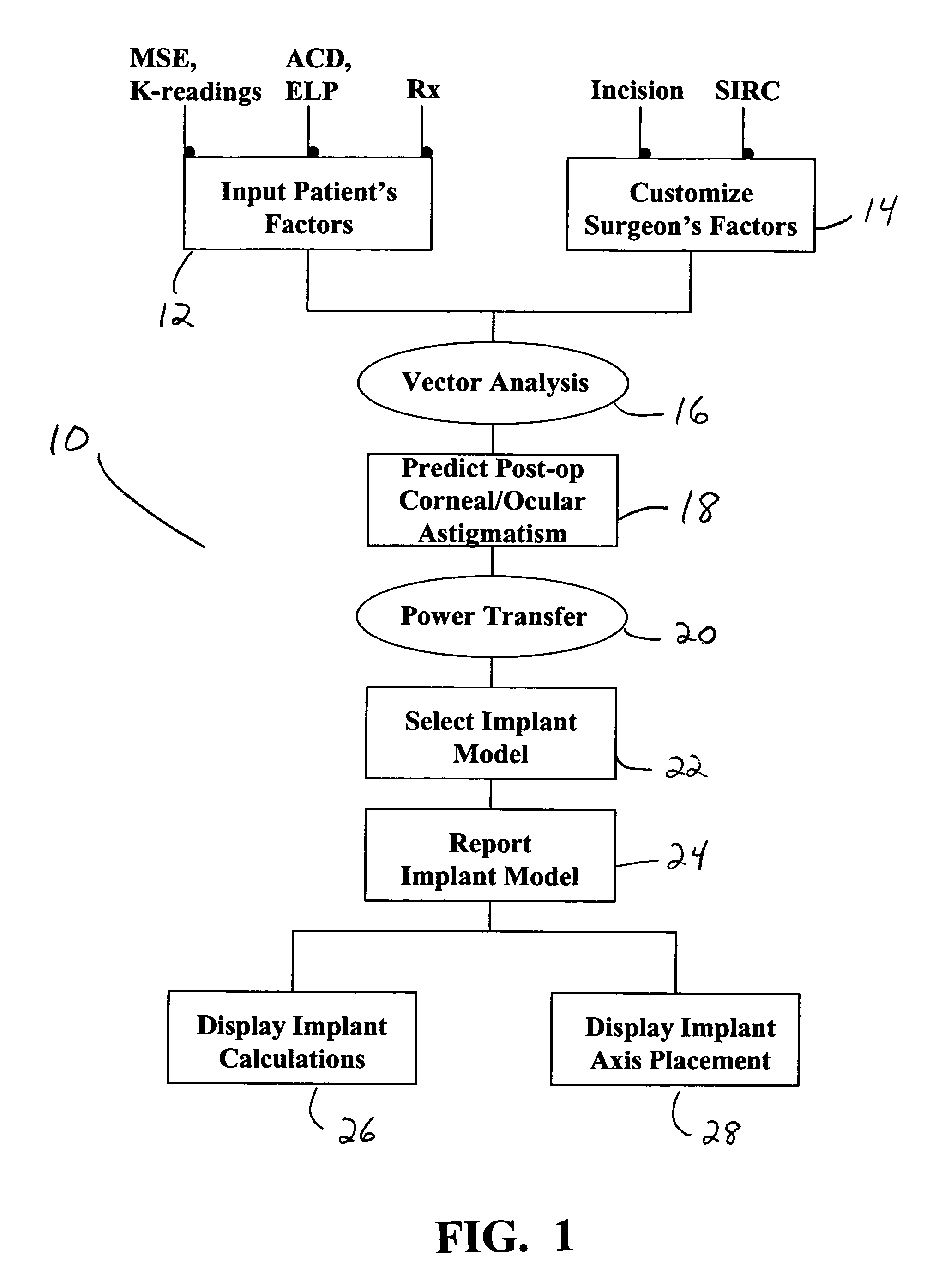
[0014]Method 10 of the present invention generally includes determining the magnitude of the astigmatic error of a patient based on patient factors and surgeon factors. Patient factors (12) include (i) the mean sphere equivalent (MSE) of the implant, (ii) the K-reading for the steepest meridian (K1) and axis (A1) and the K-reading for the flattest meridian (K2) and axis (A2), (iii) anterior chamber depth (ACD) or effective lens position (ELP) and (iv) the manifest refraction of the whole eye (in the case of calculating ocular astigmatism). Surgeon factors (14) include incision size and location (incision) and the surgically induced refractive change (SIRC) typical for the individual surgeon. Both patient factors 12 and surgeon factors 14 are analyzed at step 16 using a power vector analysis. Step 16 may use any of a variety of mathematical formulas well-known in the art, one suitable formula will now be discussed. The sphero-cylindrical prescription (S, C and α), either in optometri...


PUM


Abstract

A method for calculating the required cylindrical power of a toric implant by using both the measured pre-operative corneal / ocular astigmatism and the predicted surgically-induced astigmatism. The post-operative corneal / ocular astigmatism is predicted using power vector analysis of the surgical technique employed by the surgeon. Such a method provides a more accurate method of calculating the required spherocylindrical refractive power of the implant. The method can be implemented manually, but preferably is automated by implementation on a computer through appropriate software.

Description

BACKGROUND OF THE INVENTION[0001]This invention relates generally to the field of ophthalmic lenses and, more particularly, to toric intraocular lenses (e.g. pseudophakic IOL, AC phakic IOL, PC phakic IOL, Iris-fixed IOL and etc.).[0002]The human eye in its simplest terms functions to provide vision by transmitting light through a clear outer portion called the cornea, and focusing the image by way of a crystalline lens onto a retina. The quality of the focused image depends on many factors including the size and shape of the eye, and the transparency of the cornea and the lens.[0003]The optical power of the eye is determined by the optical power of the cornea and the crystalline lens. In the normal, healthy eye, sharp images are formed on the retina (emmetropia). In many eyes, images are either formed in front of the retina because the eye is abnormally long (axial myopia), or formed in back of the retina because the eye is abnormally short (axial hyperopia). The cornea and crystal...

Claims


Application Information

Patent Timeline
Patent Type & Authority Patents(United States)
IPC IPC(8): A61F2/14A61F2/16A61B3/00
CPCA61F2/16G02C7/028A61F2002/1645A61F2/1645A61F2240/001A61F2/142
Inventor HARRIS, BLAKEHOFFMAN, JAMESHONG, XINZHANG, XIAOXIAOHILL, WARREN E.
Owner ALCON INC
Why Eureka
Try Eureka