Pulse radar system

a pulse radar and pulse wave technology, applied in the field of pulse radar systems, can solve the problems of insufficient distance resolution between obstacles at short distances, difficult to stably control the gain of the reception pulse wave, etc., and achieve the effect of preventing a decline in the s/n ratio and high accuracy

a pulse radar and pulse wave technology, applied in the field of pulse radar systems, can solve the problems of insufficient distance resolution between obstacles at short distances, difficult to stably control the gain of the reception pulse wave, etc., and achieve the effect of preventing a decline in the s/n ratio and high accuracy

US7477182B2Inactive Publication Date: 2009-01-13TDK CORPARATION

Image

  • Pulse radar system
  • Pulse radar system
  • Pulse radar system

Examples


Embodiment Construction

[0028]A preferred embodiment will be described in detail below referring to the accompanying drawings. The present invention is not limited to the following embodiment.

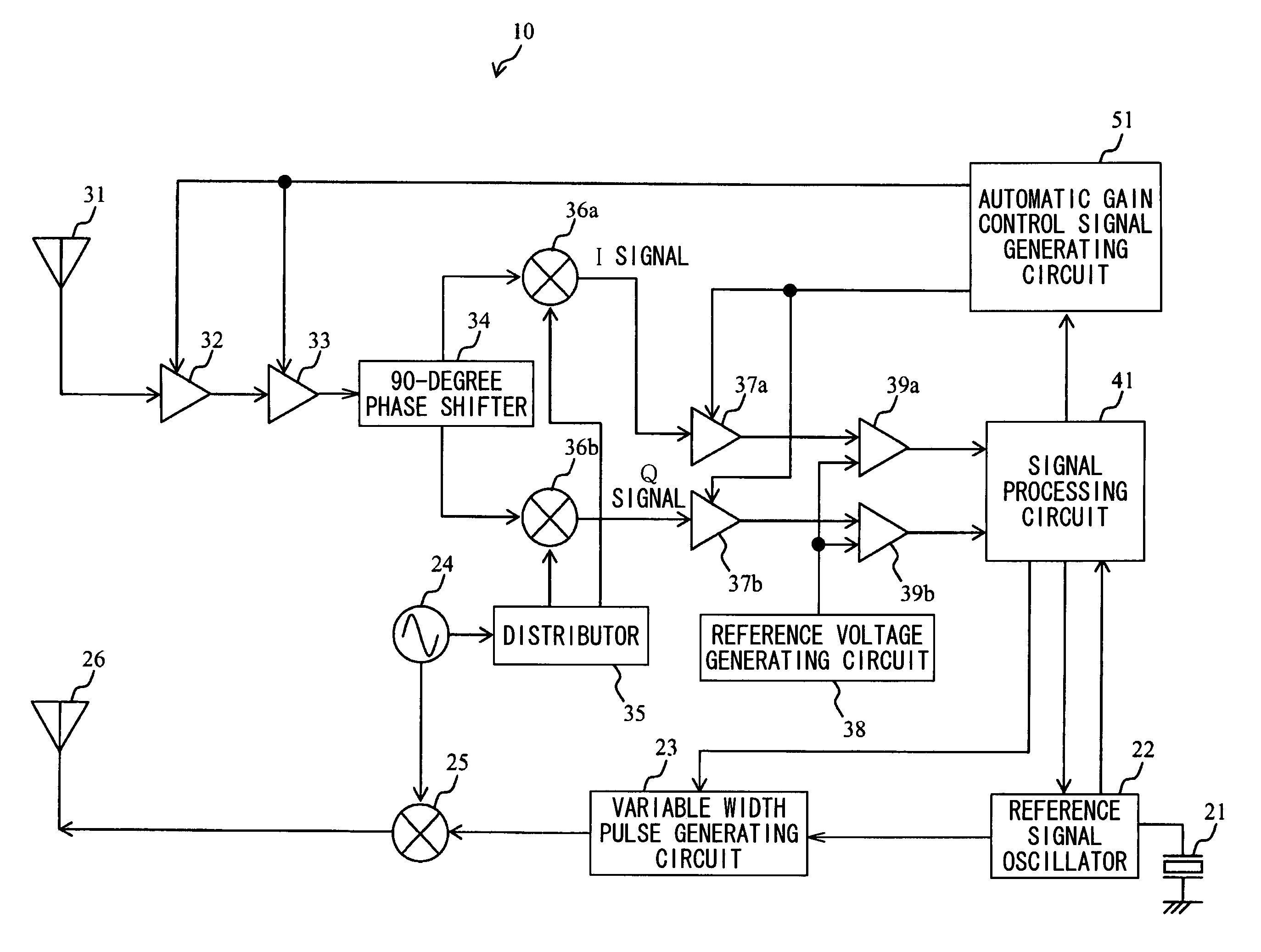
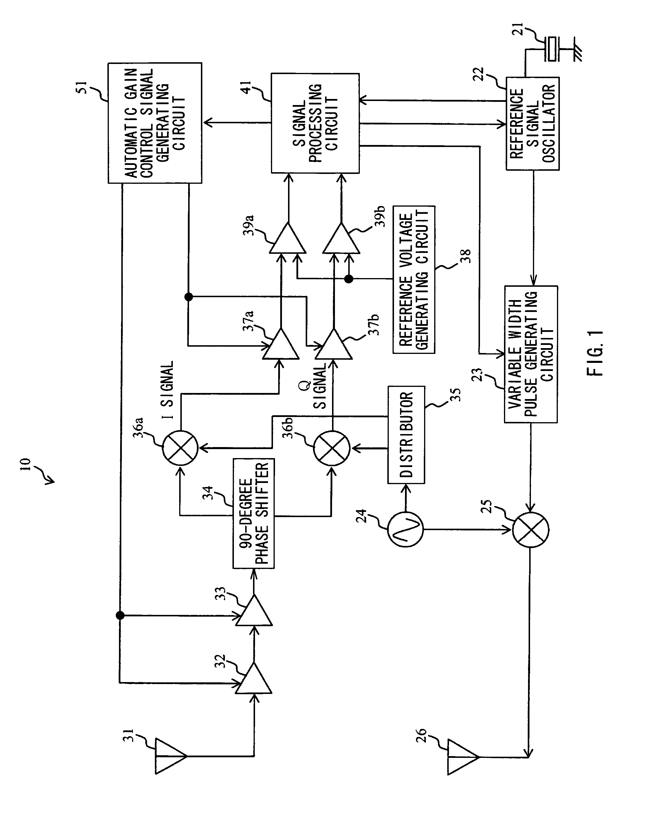
[0029]FIG. 1 shows a block diagram for describing an example of a pulse radar system according to an embodiment of the invention, and is a block diagram for describing the configuration of the pulse radar system. In FIG. 1, a reference numeral 21 designates an oscillator which outputs an oscillation signal as a reference of the pulse radar system; a reference numeral 22 designates a reference signal oscillator which divides the oscillation signal to generate a reference signal; a reference numeral 23 designates a variable width pulse generating circuit which varies the pulse widths of transmission pulses having a predetermined period generated on the basis of the reference signal and outputs the transmission pulses; a reference numeral 24 designates an oscillator which oscillates at a carrier frequency; a reference nu...


PUM


Abstract

Provided is a pulse radar system capable of measuring the distance to an obstacle with high accuracy irrespective of the distance to an obstacle by securing distance resolution with respect to a reflective wave from an obstacle at a short distance, and preventing a decline in S / N ratio with respect to a reflective wave from an obstacle at a long distance. A pulse radar system includes a transmitting circuit, a transmitting antenna, a receiving antenna, a receiving circuit, and a gain control circuit. The gain control circuit generates a gain control signal corresponding to the amplitude of the reception pulse obtained in response to a gain control transmission pulse wave transmitted from the transmitting circuit, and controls the gain of a reception pulse wave or a reception pulse obtained in response to a measurement transmission pulse wave transmitted from the transmitting circuit after the gain control transmission pulse wave.

Description

BACKGROUND OF THE INVENTION[0001]1. Field of the Invention[0002]The present invention relates to a pulse radar system using a millimeter wave band or a quasi-millimeter wave band, and particularly to a pulse radar system capable of measuring a distance by improving distance resolution or a S / N ratio with respect to a reflective wave from an obstacle at a short distance and a reflective wave from an obstacle at a long distance.[0003]2. Description of the Related Art[0004]There are pulse radar systems detecting the distance to an obstacle by transmitting a pulse wave and receiving the pulse wave reflected from the obstacle in related arts. In the pulse radar systems, a round-trip distance to an obstacle can be found by multiplying the time that elapses from the radiation of a transmission pulse wave to the reception of a reception pulse wave reflected from the obstacle, by light velocity.[0005]Such a pulse radar system measures distances to obstacles at various distances from short di...

Claims


Application Information

Patent Timeline
13 Jan 2009
Publication
US7477182B2
IPC
G01S7/34; G01S7/28; G01S13/00; G01S13/931
CPC
G01S7/34; G01S7/4004; G01S13/931; G01S2013/9375; G01S2013/9389; G01S2013/93275; G01S2013/93271
Inventors
IKEDA, HIROSHI