Loop prevention techniques using encapsulation manipulation of IP/MPLS field

a technology of encapsulation manipulation and loop prevention, applied in the field of data routing, can solve the problems of affecting the utility of affecting the overall data transfer utility, so as to prevent loops from developing at the edge of the network

Active Publication Date: 2009-01-13
CISCO TECH INC
View PDF14 Cites 30 Cited by
  • Summary
  • Abstract
  • Description
  • Claims
  • Application Information

AI Technical Summary

Benefits of technology

[0030]The present invention overcomes the disadvantages of the prior art by providing a fast reroute (FRR) technique that may be implemented at the edge of a computer network. In accordance with the technique, if an edge device detects a node or link failure that prevents it from communicating with a neighboring routing domain, the edge device reroutes at least some data packets addressed to that domain to a backup edge device which, in turn, forwards the packets to the neighboring domain. The rerouted packets are designated as being “protected” (i.e., rerouted) data packets before they are forwarded to the backup edge device. To that end, the edge device incorporates an identifier into the rerouted data packets to indicate that the packets are being FRR rerouted. The identifier may be a predetermined value stored at a known location in the rerouted packets'encapsulation headers, such as in their MPLS or IP headers. Upon receiving a data packet containing the identifier, the backup edge device is not permitted to reroute the packet a second time, e.g., in response to another inter-domain node or link failure, thereby preventing loops from developing at the edge of the network.
[0031]Advantageously, the inventive technique provides a fast and efficient way for a backup edge device to identify protected data packets that have been previously rerouted in response to, e.g., a CE node or PE-CE link failure. The technique is not limited to MPLS / VPN network architectures and may be deployed at the edge of networks implementing various topologies and protocols. Further, the invention is not limited to any particular hardware platform or set of software capabilities.

Problems solved by technology

For example, the node may become unable to communicate with one of its neighboring nodes, e.g., due to a link failure between the nodes or the neighboring node failing, such as going “off line” for repairs.
Problems arise in the conventional MPLSIVPN architecture when a node or link failure prevents data communications over a PE-CE data link.
The conventional latency required for the PE devices to converge on the new network topology, i.e., without the PE1-CE1 link, is often overly time consuming, e.g., on the order of seconds, and causes a number of significant problems.
For many data flows, such as voice-over-IP (VoIP) and video data flows, this temporary loss of data at PE1 may significantly degrade the utility of the overall data transfer or may cause the data flow to time-out and stop completely.

Method used


Image

  • Loop prevention techniques using encapsulation manipulation of IP/MPLS field
  • Loop prevention techniques using encapsulation manipulation of IP/MPLS field
  • Loop prevention techniques using encapsulation manipulation of IP/MPLS field

Examples


Embodiment Construction

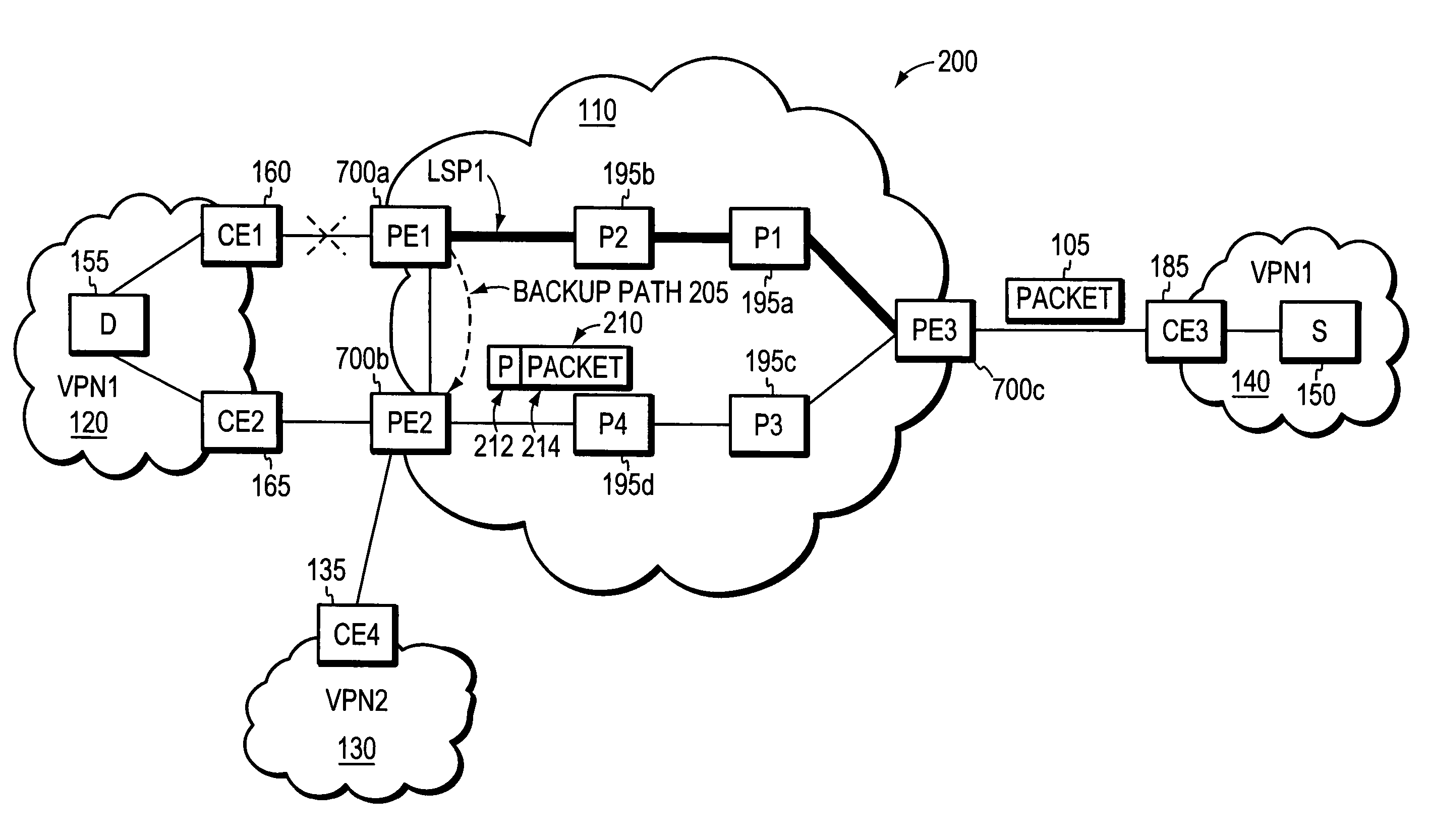
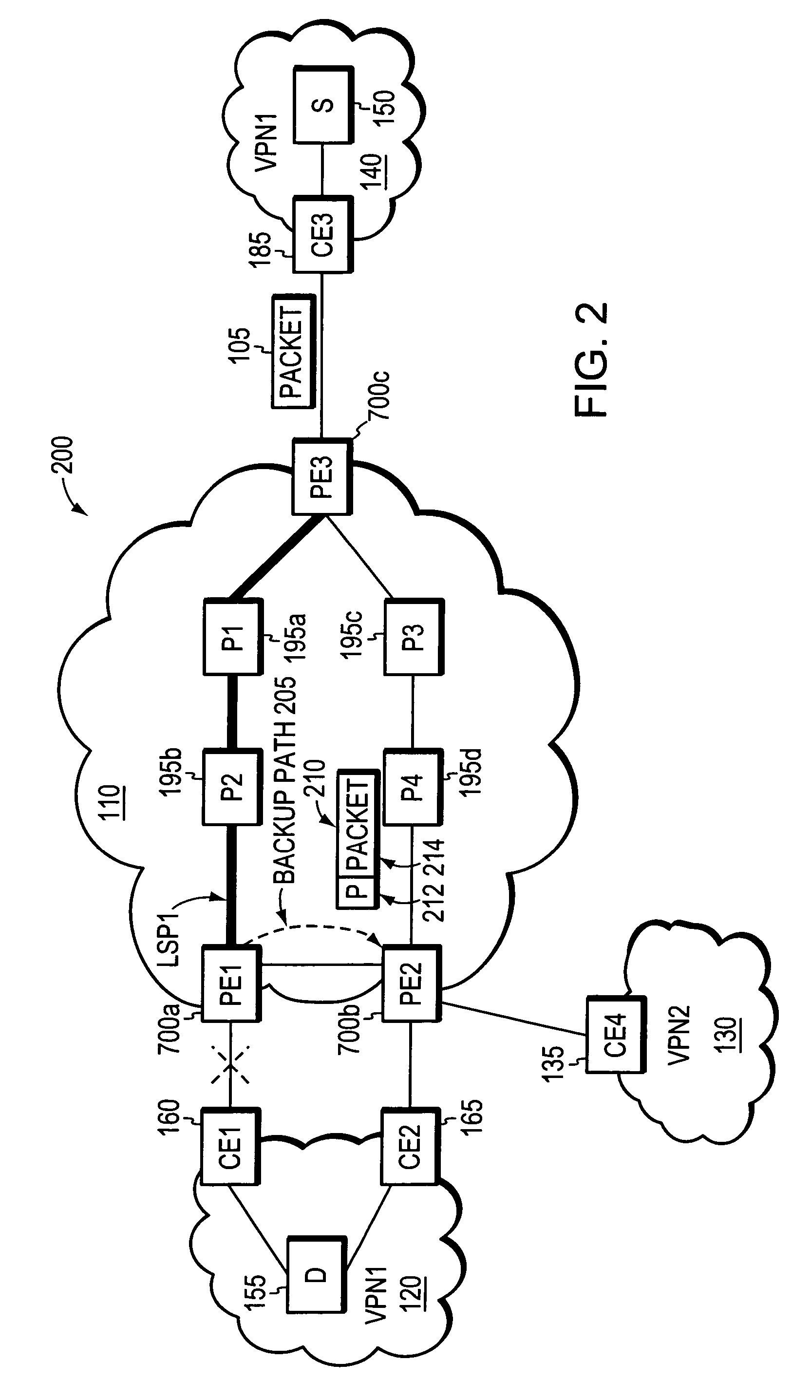
[0042]In accordance with the illustrative embodiments, if an edge device detects a node or link failure that prevents it from communicating with devices in a neighboring domain, the edge device reroutes at least some data packets addressed to the neighboring domain to a backup edge device. The rerouted packets are preferably “tunneled” to the backup edge device, e.g., using an IP or MPLS tunneling mechanism. After receiving the rerouted packets, the backup edge device forwards the packets to the neighboring domain. Notably, the backup edge device is not permitted to reroute the received packets a second time, e.g., upon identifying another inter-domain node or link failure. As such, packet loops are avoided at the edge of the network.

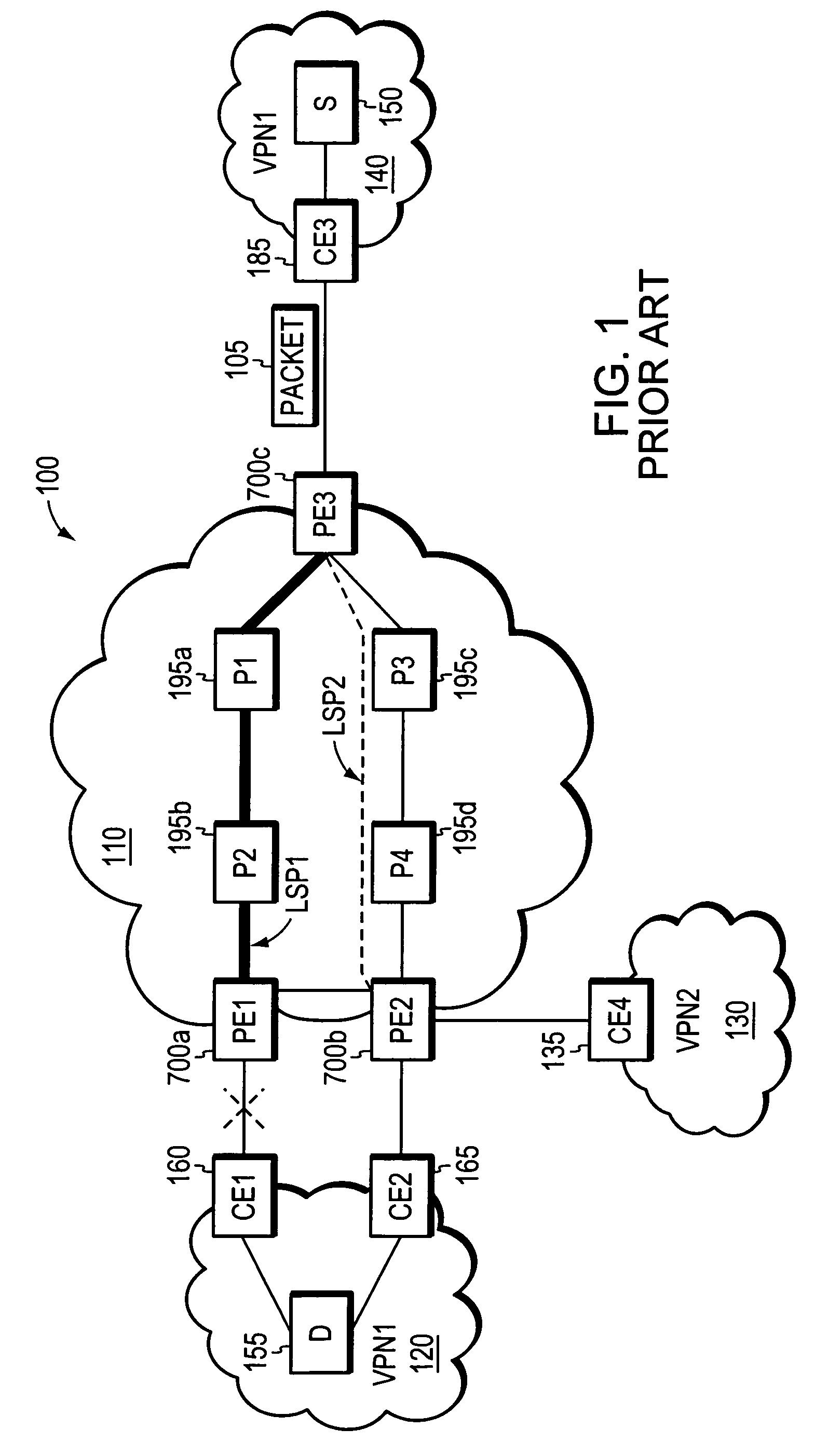
[0043]FIG. 2 illustrates a computer network 200 employing an illustrative embodiment of the invention. For ease of explanation, the network topology of network 200 is the same as that shown in FIG. 1. However, unlike in the network 100, the provider edg...


PUM


Abstract

A fast reroute (FRR) technique is implemented at the edge of a computer network. In accordance with the technique, if an edge device detects a node or link failure that prevents it from communicating with a neighboring routing domain, the edge device reroutes at least some data packets addressed to that domain to a backup edge device which, in turn, forwards the packets to the neighboring domain. The rerouted packets are designated as being “protected” (i.e., rerouted) data packets before they are forwarded to the backup edge device. To that end, the edge device incorporates an identifier into the rerouted data packets to indicate that the packets are being FRR rerouted. The identifier may be a predetermined value stored at a known location in the rerouted packets'encapsulation headers, such as in their MPLS or IP headers. Upon receiving a data packet containing the identifier, the backup edge device is not permitted to reroute the packet a second time.

Description

RELATED APPLICATIONS[0001]This application is related to U.S. patent application Ser. No. 11 / 010,225, entitled FAST REROUTE (FRR) PROTECTION AT THE EDGE OF A RFC 2547 NETWORK, filed Dec. 10, 2004, by Clarence Filsfils et al., the teachings of which are expressly incorporated herein by reference.[0002]This application is related to U.S. patent application Ser. No. 11 / 046,163, entitled LOOP PREVENTION TECHNIQUE FOR MPLS USING TWO LABELS, filed Jan. 26, 2005, by Clarence Filsfils et al., the teachings of which are expressly incorporated herein by reference.[0003]This application is related to U.S. patent application Ser. No. 10 / 608,495, entitled LOOP PREVENTION TECHNIQUE FOR MPLS USING SERVICE LABELS, filed Feb. 28, 2005, by Clarence Filsfils et al., the teachings of which are expressly incorporated herein by reference.FIELD OF THE INVENTION[0004]This invention relates generally to routing data between private routing domains, and, more specifically, to a fast reroute (FRR) technique t...

Claims


Application Information

Patent Timeline
Patent Type & Authority Patents(United States)
IPC IPC(8): H04L12/56H04L45/02H04L45/24H04L45/28H04L45/50
CPCH04L45/02H04L45/22H04L45/28H04L45/50H04L47/2408
Inventor SCUDDER, JOHN GALENWARD, DAVID D.FILSFILS, CLARENCE
Owner CISCO TECH INC
Why Eureka
Try Eureka