
Data collection using sensing units and separate control units with all power derived from the control units

a data collection and control unit technology, applied in the field of collecting and transmitting data, can solve the problems of data inefficiency, data collection, and system inability to generally sense, collect and store data,

Inactive Publication Date: 2009-01-13
LORD CORP
View PDF27 Cites 223 Cited by
  • Summary
  • Abstract
  • Description
  • Claims
  • Application Information

AI Technical Summary

Benefits of technology

[0016]It is an advantage of the present invention that the data collection device can provide real time data triggered by an event or by a user in response to a change in information about the structure or live subject.
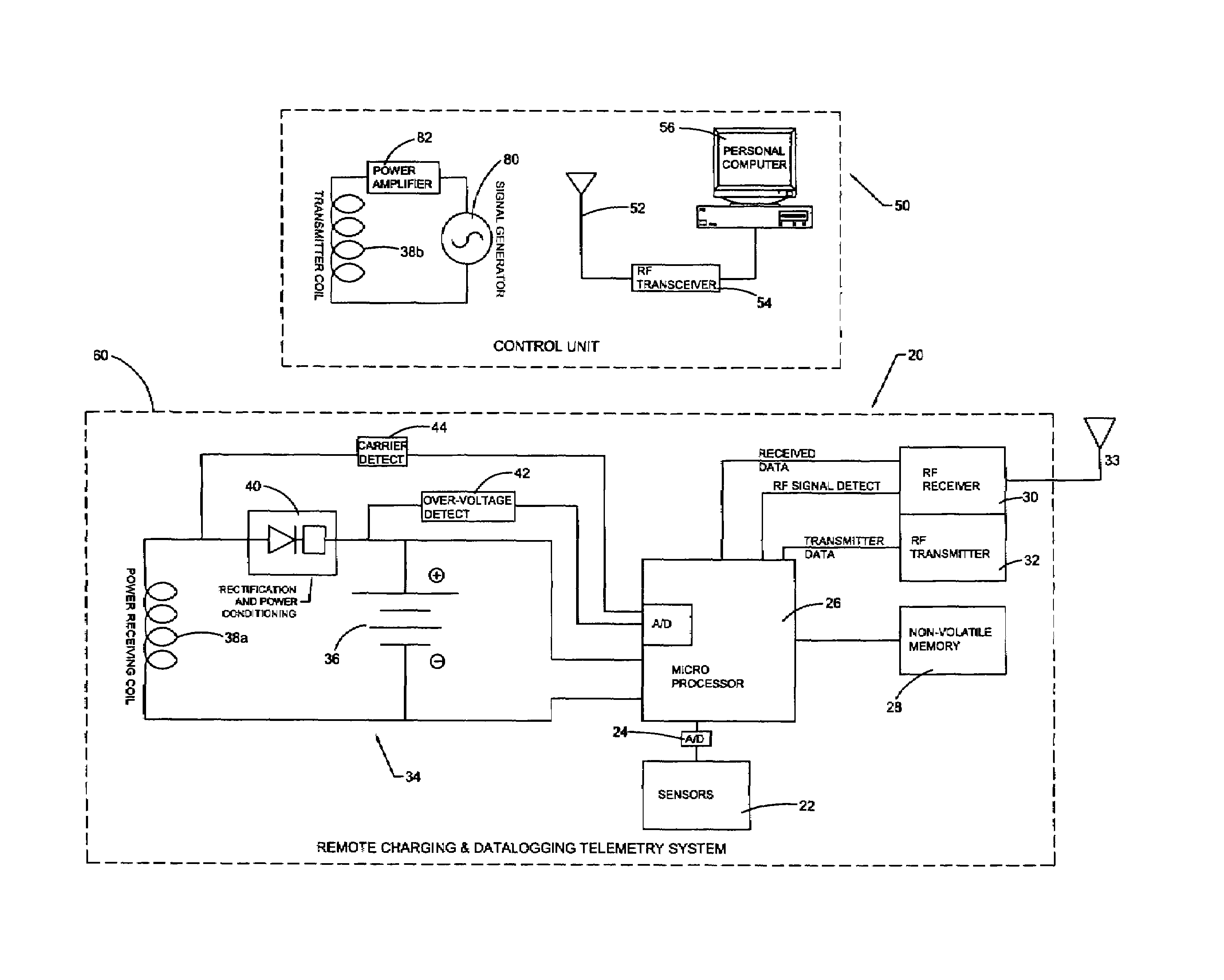
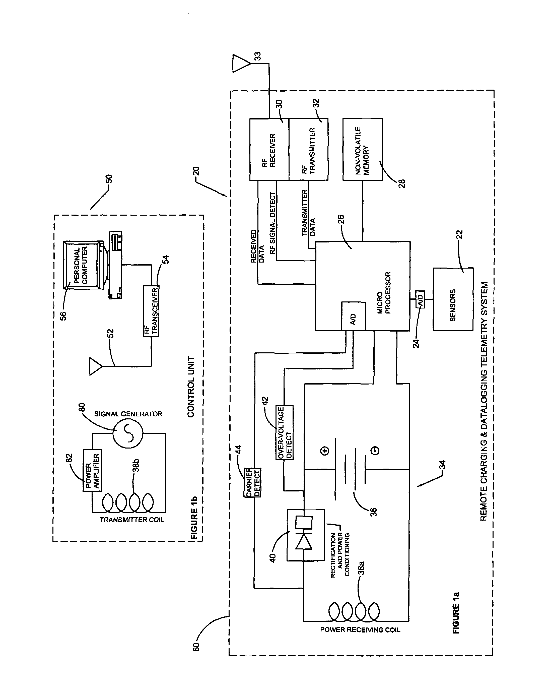
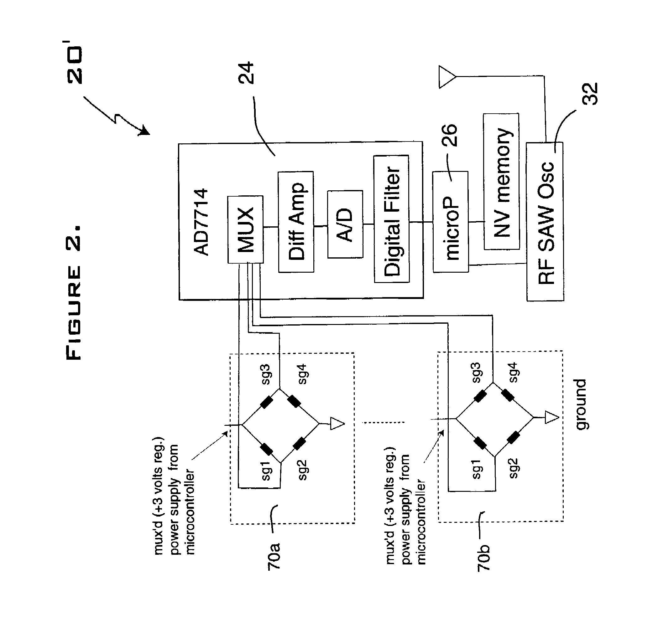
[0017]These and other objects, features, and advantages of the invention are accomplished by a data collection apparatus that includes a sensing unit for attaching to a structure or live subject for sensing a parameter of the structure or live subject. The sensing unit includes a sensor, a data storage device, and a transmitting device. The data storage device is for storing data from the sensor. The apparatus also includes a control unit that is separable from the sensing unit. The control unit includes a data receiving device and a second data storage device different from said first storage device. The data receiving device is to receive data transmitted from the data sensing unit. The second data storage device is for storing the data received from the sensing unit. The apparatus also includes a triggering device for modifying the storing of data being stored to the first data storage device or for initiating transmission of data from the sensing unit to the control unit. The triggering device is controlled by a real time change in information about the structure or live subject.

Problems solved by technology

These systems do not generally sense, collect, and store data though.
All the systems that sense and collect data, store the data, and then communicate the data have inefficiencies either in the data acquisition or in the transmission of the data.

Method used


Image

  • Data collection using sensing units and separate control units with all power derived from the control units
  • Data collection using sensing units and separate control units with all power derived from the control units
  • Data collection using sensing units and separate control units with all power derived from the control units

Examples


Embodiment Construction

[0025]The present inventors recognized that substantial efficiency in collecting, storing, and transmitting data could be provided. They recognized that data from a moving or remote structure or live subject may be provided by mounting a sensing unit in or on the structure or subject of interest. In one embodiment, the sensing unit has both a sensor and a data storage device for storing data from the sensor. The inventors further recognized that providing a scheme in which the data storage is controlled by a real time trigger solves a problem with previously existing systems.

[0026]In one embodiment of the invention, accelerometers, data storage, and a triggering scheme are mounted in a wearable device such as a sports helmet. The triggering scheme can be data collected by the accelerometers that exceeds a predetermined threshold. The above-threshold data may be caused by an event, such as a collision. If the high acceleration produced by a collision and measured by the accelerometer...


PUM


Abstract

A data collection apparatus includes a sensing unit for attaching to a structure or live subject for sensing a parameter of the structure or live subject. The sensing unit includes a sensor, a data storage device, and a transmitting device. The data storage device is for storing data from the sensor. The apparatus also includes a control unit that is separable from the sensing unit. The control unit includes a data receiving device and a second data storage device different from said first storage device. The data receiving device is to receive data transmitted from the data sensing unit. The second data storage device is for storing the data received from the sensing unit. The apparatus also includes a triggering device for modifying the storing of data being stored to the first data storage device or for initiating transmission of data from the sensing unit to the control unit. The triggering device is controlled by a real time change in information about the structure or live subject.

Description

[0001]This application claims priority of U.S. Provisional Patent Application 60 / 169,364, filed Dec. 6, 1999.FIELD OF THE INVENTION[0002]This invention generally relates to collecting and transmitting data. More particularly, it relates to a device for sensing, storing and transmitting data. Even more particularly, it relates to a device that can be attached to a structure or live subject for providing data about the structure or live subject.BACKGROUND OF THE INVENTION[0003]Art, photography, and scientific literature record long standing interest in how humans or animals run, and details of what happens in a collision. Various systems for sensing, collecting, storing, and communicating data about moving systems and remote locations have been described in the literature.[0004]For example, in virtual reality systems the motion of the head and other extremities is continuously monitored to provide feedback to the computer to enable updating of images, as mentioned in U.S. Pat. No. 5,9...

Claims


Application Information

Patent Timeline
IPC IPC(8): G06F17/00G08B23/00A61B5/00G08B21/04
CPCG08B21/0446G08B21/0453A61B5/4504A61B5/002A61B5/0022Y10S707/99945Y10S707/99948
Inventor TOWNSEND, CHRISTOPHER P.ARMS, STEVEN W
Owner LORD CORP
Learn More