Big wheel motive power source

a power source and big wheel technology, applied in the field of power sources, can solve the problems of excessive weight of the flywheel, minimal speed, and huge wear of parts and materials, and achieve the effect of increasing power, power and fuel economy, and reducing weigh

Inactive Publication Date: 2009-01-20
CURTIS BRENT EDWARD
View PDF33 Cites 27 Cited by
  • Summary
  • Abstract
  • Description
  • Claims
  • Application Information

AI Technical Summary

Benefits of technology

[0017]Until now, conventional vehicles have been made as light as possible in order to obtain decent fuel economy. Contrary to same, and unexpectedly, the big wheel motive power source provides a system in which the heavier the wheel, the more efficient the engine. Namely, power and fuel economy are gained by weight, as more weight translates into more power and better fuel economy for a vehicle.
[0018]Accordingly, it is a primary object of the present invention to provide a power source with improved fuel economy and reduced emissions produced by the energy generated from the rotation of a large mass wheel.

Problems solved by technology

Unfortunately, current flywheel systems incorporate a flywheel which is too light in relation to the vehicle to which it is applied.
As a result, the power generated by the flywheel will either be rapidly used, requiring almost continuous recharging, or supply very low motive power to the vehicle, resulting in minimal speed.
However, such high speed causes tremendous wear on parts and materials and, in fact, requires extremely high strength material to construct and maintain within the power source.
Moreover, the high speed flywheel may require a large expense of energy to bring the rotational velocity up to speed.
However, such devices also typically contemplate that the vehicle can be started and driven directly from the primary engine, which is a standard / conventional vehicle engine, without the assistance of the flywheel.
Further, while providing a spinning wheel, the spinning wheel is typically not geared up to a level of speed to be an effective form of energy output.
In general, disadvantages inherent in many such designs are, among other things, without a transmission between the primary engine and the flywheel, the systems are not durable enough to last very long.
Namely, if a flywheel is provided of sufficient weight to generate enough power to motivate a vehicle, it would need a transmission between the primary motor and the flywheel or it would place too much strain on either the engine or the clutch.
However, if the flywheel provided is lightweight, so as to avoid the need for a transmission, it would be ineffective in generating sufficient motive power.
In such cases, the flywheel is prone to wobble, and causes significant wear on the lower component holding or supporting same in place.
Moreover, many such systems incorporate a flywheel that is not heavy enough to generate effective, efficient motive power.
Moreover, the flywheel is generally not appropriately geared to the vehicle wheels at a ratio effective to convey sufficient motive power from the flywheel alone.
To date, an effective, efficient system has not been available in which a large mass rotating wheel generates the primary motive power for a vehicle, machine, or device.

Method used


Image

  • Big wheel motive power source
  • Big wheel motive power source
  • Big wheel motive power source

Examples


Embodiment Construction

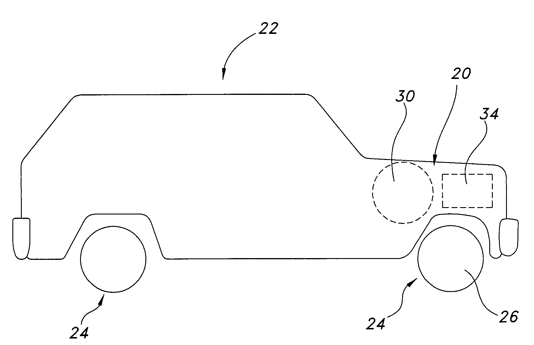
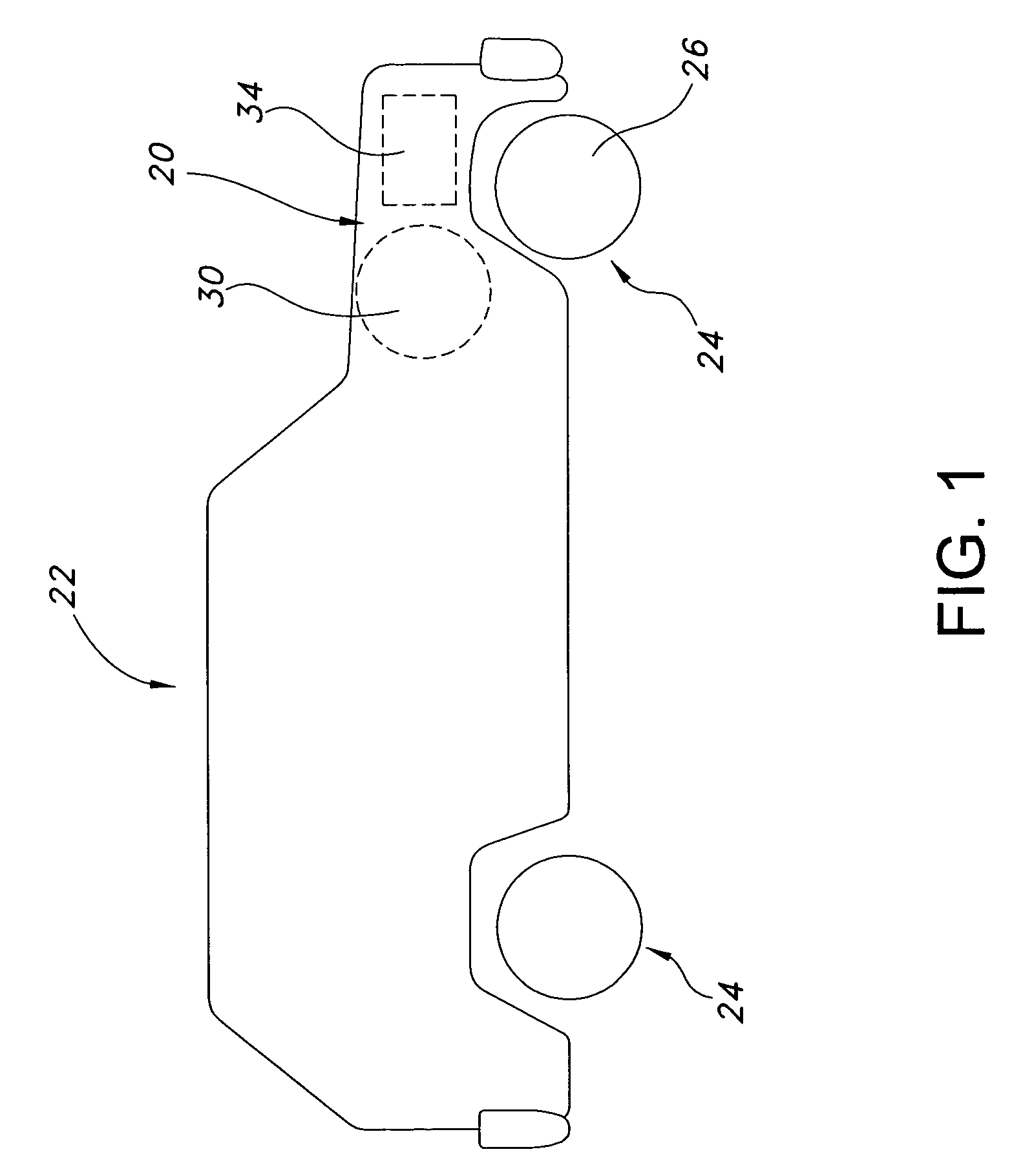
[0031]The present inventive big wheel motive power source is embodied in a vehicle. More specifically, the big wheel motive power source shown and described is for use with a front wheel drive vehicle.

[0032]Referring to the Figures, the big wheel motive power source 20 of the present invention is shown in connection with a vehicle 22. However, the invention is not limited thereto, as one of ordinary skill in the art would understand that the big wheel motive power source 20 may be adapted to fit any machine, vehicle, or device. Likewise, one of ordinary skill in the art would understand that the present invention may be used in combination with any vehicle employing front wheel, rear wheel, or four wheel drive without departing from the scope of the present invention.

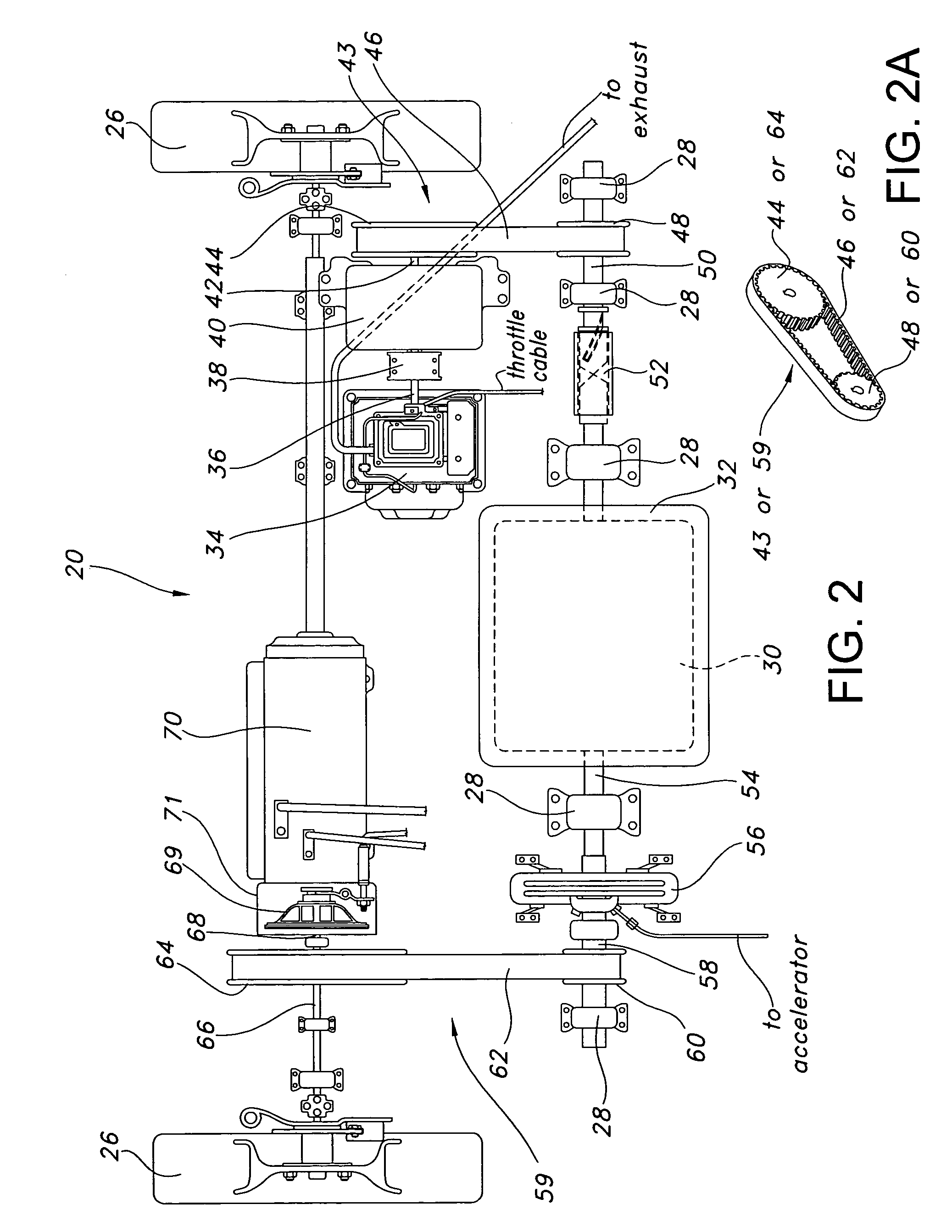
[0033]Preferably, the big wheel motive power source 20 of the present invention comprises a power source for generating movement or motive power, in which the power source comprises a wheel capable of rotation, and havi...


PUM


Abstract

A big wheel motive power source is provided. The big wheel motive power source comprises a large mass wheel capable of rotation and having a mass comprising at least one-third the weight of a vehicle in which it is located, or at least twice the weight of a conventional engine for that vehicle. A small horsepower, continuously running engine is operably connected to the large mass wheel and generates the rotation of large mass wheel. The large mass wheel may be further connected to at least one driven wheel, whereby the rotation of the large mass wheel provides a primary motive power source for a vehicle. A ratchet-type worm engaged drive, a control system, and a exhaust removal system are also disclosed for use with the present inventive device.

Description

FIELD OF THE INVENTION[0001]The present invention relates to the art of power sources for vehicles, machines, and other devices and, more specifically, to a big wheel motive power source as a primary motive power source for a vehicle.BACKGROUND[0002]Conventional thought with respect to power systems for vehicles has been to design a lightweight vehicle for fuel efficiency. It is generally believed that a vehicle that is of lighter weight will require less power to motivate, and therefore will require less fuel input to accomplish the same power output as a heavier vehicle. Consistent with same, traditional vehicle design has been directed toward the use and / or development of light and / or small components that ultimately reduce the weight of the vehicle in which they are placed.[0003]In connection with, and in addition to lightweight vehicles and components, various alternative power sources have been experimented with, including, for example, electric vehicles, hybrid electric vehic...

Claims


Application Information

Patent Timeline
Patent Type & Authority Patents(United States)
IPC IPC(8): B60K6/00
CPCB60K6/105Y02T10/6204Y02T10/62
Inventor CURTIS, BRENT EDWARD
Owner CURTIS BRENT EDWARD
Why Eureka
Try Eureka