Backlight unit with an oxide compound-laminated optical layer

a technology of backlight unit and optical layer, which is applied in the field of backlight unit, can solve the problems of low light emission efficiency, reduced red color ability of light source thus produced, and difficulty in developing fluorescent bodies, so as to improve light emission efficiency and color purity. the effect of ligh

Inactive Publication Date: 2009-01-20
SAMSUNG CORNING PRECISION MATERIALS CO LTD
View PDF2 Cites 29 Cited by
  • Summary
  • Abstract
  • Description
  • Claims
  • Application Information

AI Technical Summary

Benefits of technology

[0019]It is, therefore, an object of the present invention to provide a backlight unit capable of improving a light emitting efficiency and a color purity of a light through the use of optical resonance in an optical layer.
[0020]In accordance with the present invention, there is provided a backlight unit for use in a liquid crystal display having a liquid crystal panel, comprising: a substrate; a plurality of light sources arranged on the substrate in a spaced-apart relationship with one another for irradiating lights; a total reflection layer for reflecting the lights irradiated from the light sources in an upward direction; and an optical layer disposed above the light sources and having an oxide compound layer laminated thereon, the optical layer adapted to allow a part of the lights to pass through the optical layer but reflect the remaining part of the lights downwardly toward the substrate, whereby the backlight unit can induce the lights irradiated from the light sources to optically resonate.

Problems solved by technology

A cathode ray tube (“CRT”), one of typical display devices, has been extensively used in television sets or computer monitors, but fails to catch up with the recent trend of miniaturization and lightweight of electronic equipments.
The method of taking advantage of a blue color light emitting diode and an yttrium aluminum garnet (“YAG”) fluorescent body is disadvantageous in that the light source thus produced has a reduced ability to express the red color and a low light emitting efficiency.
Likewise, the method of using an ultraviolet emitting diode in combination with fluorescent bodies of red, green and blue colors poses a drawback in that it is difficult to develop the fluorescent bodies, with the resultant light source exhibiting a deteriorated thermal characteristic.
However, the method has a problem in that it is difficult to compose a combination of diodes for a white surface light source.
However, the light emitting diodes developed thus far cannot provide a sufficiently great light emitting efficiency, due to the light loss when penetrating a current diffusion layer and the light loss caused by a total reflection at a boundary surface.
In the case that an increased current is applied to a light emitting diode, a great deal of heat is generated from the light emitting diode, thus reducing the light emitting efficiency and making it necessary to add a heat radiation design to a substrate on which the light emitting diode is mounted.
In the event that the number of light emitting diodes is increased, it becomes difficult to design the backlight unit, in addition to the increase of production cost of the backlight unit.
Although nitride semiconductor-based light emitting diodes and InGaAlP-based light emitting diodes have been developed for the purpose of enhancing the light emitting efficiency, they tend to emit a light whose flux is lower than that of a cold cathode fluorescent lamp and therefore are not suitable for use in a backlight unit.

Method used


Image

  • Backlight unit with an oxide compound-laminated optical layer
  • Backlight unit with an oxide compound-laminated optical layer
  • Backlight unit with an oxide compound-laminated optical layer

Examples


Embodiment Construction

[0030]Hereinafter, preferred embodiments of the present invention will be described in detail with reference to the accompanying drawings.

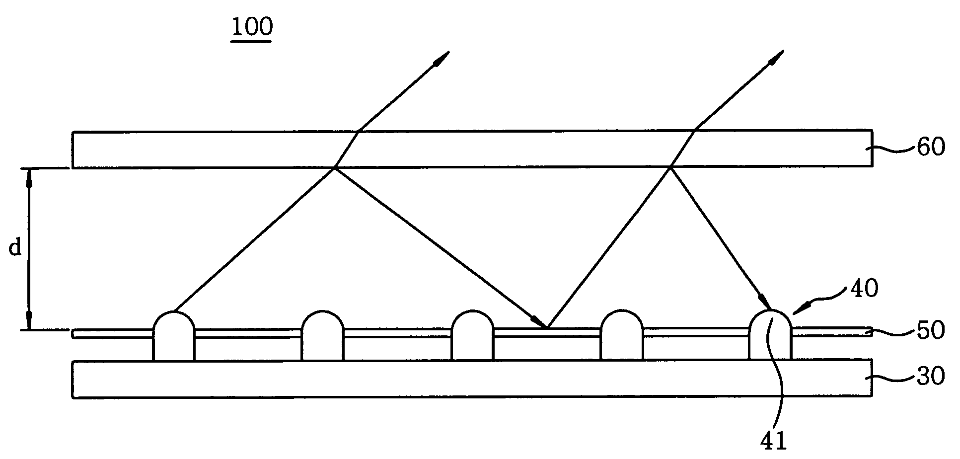
[0031]FIG. 3 is a front elevational view depicting a part of a backlight unit in accordance with the present invention, and FIGS. 4A and 4B are front elevational views showing laminated structures of an oxide compound in the optical layer shown in FIG. 3.

[0032]As shown in FIG. 3, a backlight unit 100 in accordance with the present invention includes a substrate 30, a plurality of light emitting diodes 40 arranged on the substrate 30 in a spaced-apart relationship with one another, a total reflection layer 50 for reflecting a light irradiated from the light emitting diodes 40 in an upward direction, i.e., toward a liquid crystal layer, and an optical layer 60 provided above the light emitting diodes 40 for allowing a part of the light to be transmitted therethrough and reflecting the remaining part of the light toward the substrate 30.

[0033]The sub...


PUM


Abstract

A backlight unit includes a substrate, a plurality of light sources arranged on the substrate in a spaced-apart relationship with one another for irradiating lights, a total reflection layer for upwardly reflecting the lights irradiated from the light sources, and an optical layer disposed above the light sources and having an oxide compound layer laminated thereon. The optical layer is adapted to allow a part of the lights to pass through the optical layer but reflect the remaining part of the lights downwardly toward the substrate, to thereby induce the lights from the light sources to optically resonate. The optical resonance caused by the oxide compound-laminated optical layer helps to reduce the half amplitude of a color-based spectrum histogram in a light-emitting spectrum, thereby enhancing the color purity.

Description

FIELD OF THE INVENTION[0001]The present invention relates to a backlight unit, and more specifically, to a backlight unit capable of increasing a luminance through the use of optical resonance in an optical layer.BACKGROUND OF THE INVENTION[0002]A cathode ray tube (“CRT”), one of typical display devices, has been extensively used in television sets or computer monitors, but fails to catch up with the recent trend of miniaturization and lightweight of electronic equipments.[0003]Thus, a variety of technologies have been developed in an effort to replace the cathode ray tube with new display devices, examples of which include a liquid crystal display (“LCD”) using an electric field optical effect, a plasma display panel (“PDP”) using a plasma discharge and an electroluminescence display (“ELD”) using an electric field light-emitting effect.[0004]Among these devices, the liquid crystal display, which features thin lightweight configuration and low electricity operability, is showing ra...

Claims


Application Information

Patent Timeline
Patent Type & Authority Patents(United States)
IPC IPC(8): F21V5/00
CPCG02F1/133603
Inventor CHOI, YONG WON
Owner SAMSUNG CORNING PRECISION MATERIALS CO LTD
Why Eureka
Try Eureka