Duplexer

a duplexer and constant line technology, applied in the field of duplexers, can solve the problems of large capacity coupling between adjacent inductors on the dielectric film, device size and height cannot be minimized or shorten, and the conventional duplexer with a distributed constant line cannot be made smaller or shorter, etc., to achieve excellent filter characteristics, low in-band insertion loss, and high isolation characteristics

Active Publication Date: 2009-01-20
TAIYO YUDEN KK
View PDF29 Cites 35 Cited by
  • Summary
  • Abstract
  • Description
  • Claims
  • Application Information

AI Technical Summary

Benefits of technology

[0008]A more specific object of the present invention is to provide a duplexer with excellent filter characteristics that exhibit low in-band insertion loss and high isolation characteristics, though the duplexer is small in size.
[0012]The present invention can provide a duplexer with excellent filter characteristics that exhibit low in-band insertion loss and high isolation characteristics, though the duplexer is small in size.

Problems solved by technology

However, a conventional duplexer with a distributed-constant line cannot be made smaller or shorter, because a very long line is required as the distributed-constant line.
With such a structure, the device cannot be minimized in size and height.
However, with a dielectric film being formed on an insulating substrate, the capacity coupling between adjacent inductors on the dielectric film becomes large due to the large dielectric constant of the dielectric film.
As a result, the loss increases because of the resonance caused between the adjacent inductors, and the isolation characteristics deteriorate due to the coupling between the adjacent inductors.
For this reason, the lumped-constant inductor and the capacitor disclosed in U.S. Pat. No. 5,175,518 are not suitable for the phase-matching circuits of SAW filters that need to exhibit low insertion loss in the band and high isolation characteristics.
This presents the problem in producing a duplexer with excellent filter characteristics.

Method used


Image

  • Duplexer
  • Duplexer
  • Duplexer

Examples


first embodiment

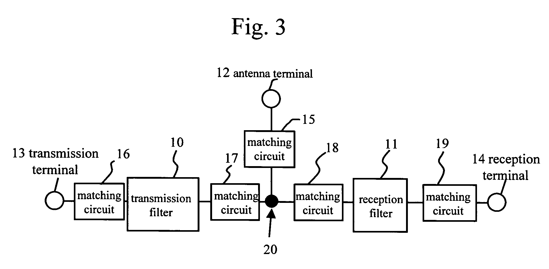
[0038]FIG. 3 is a block diagram of a duplexer in accordance with a first embodiment of the present invention. The duplexer includes a transmission filter 10, a reception filter 11, an antenna terminal (a common terminal) 12, a transmission terminal 13, and 1 reception terminal 14. The transmission filter 10 and the reception filter 11 are surface acoustic wave (SAW) filters. In the following, the transmission filter 10 and the reception filter 11 may also be referred to as a transmission SAW filter 10 and a reception SAW filter 11. The duplexer also includes phase matching circuits 15 through 19. However, the duplexer of the present invention does not need to include the phase matching circuits 15 through 19. Rather, the phase matching circuits 15 through 19 are selectively employed so as to obtain desired characteristics. For example, only the matching circuit 18 may be employed. The matching circuits in the duplexer are reactance circuits that are formed with lumped-constant react...

second embodiment

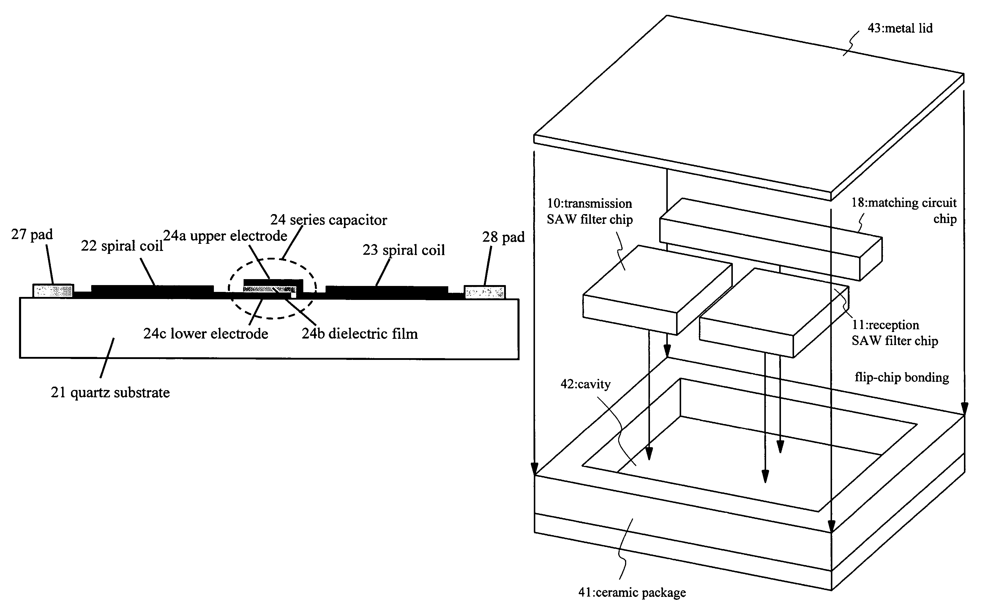
[0047]FIG. 11A illustrates a duplexer of a second embodiment that has a matching circuit 18 on the input side of a reception filter 11 and a matching circuit 19 on the output side of the reception filter 11. As shown in FIG. 11B, the two matching circuits 18 and 19 are formed on a quartz substrate 21 that is an insulating substrate. A filter chip 44 having the quartz substrate 21 shown in FIG. 11B includes not only the components shown in FIG. 5A, but also an inductor L3 that forms the matching circuit 19, and a reception terminal connecting pad 45 and a reception filter connecting pad 46 that are connected to both ends of the inductor L3. Like the inductors 22 and 23, the inductor L3 is in a spiral form, and is formed directly on the surface of the quartz substrate 21. Accordingly, not only the capacity coupling between the inductors L1 and L2 forming the matching circuit 18 but also the capacity coupling between the inductor L3 of the matching circuit 19 and the inductors L1 and L...

third embodiment

[0049]FIG. 13 is a plan view of a duplexer of a third embodiment of the present invention. This duplexer has a structure in which a transmission filter 10 and a reception filter 11 formed with SAW filters, parallel inductors 62 and 63, and a series capacitor 64 are formed on a single piezoelectric substrate 51. The parallel inductors 62 and 63 and the series capacitor 64 form the matching circuit 18 (see FIG. 3) with the circuit structure illustrated in FIG. 4B. The parallel inductors 62 and 63 are spiral coils, and the series capacitor 64 has the structure illustrated in FIG. 5B, for example. An antenna terminal connecting pad 52, a transmission terminal connecting pad 53, a reception terminal connecting pad 54, and ground pads 55 and 56 are also formed on the piezoelectric substrate 51. As the transmission filter 10, the reception filter 11, and the matching circuit 18 are formed on the single piezoelectric substrate 51, the number of required components is reduced, and the duplex...


PUM


Abstract

A duplexer that includes: a transmission filter and a reception filter that are connected to a common terminal; and a reactance circuit that is connected to at least one of the transmission filter and the reception filter. The reactance circuit includes an insulating substrate, lumped-constant inductors, and at least one capacitor. The lumped-constant inductors and the capacitor are formed directly on the surface of the insulating substrate.

Description

BACKGROUND OF THE INVENTION[0001]1. Field of the Invention[0002]The present invention generally relates to duplexers, and more particularly, to a duplexer that utilizes surface acoustic wave (SAW).[0003]2. Description of the Related Art[0004]So as to separate transmission and reception signals from other signals, antenna duplexers with surface acoustic wave (SAW) filters are mounted in most mobile-phone handsets today. Each of the SAW duplexers includes a transmission SAW filter, a reception SAW filter, and a matching circuit that is interposed between the reception filter and the connecting point of the transmission and reception filters. This matching circuit is provided for guiding each transmission signal from the transmission filter toward an antenna terminal and for preventing each transmission signal from flowing into the reception filter. Normally, the matching circuit is formed with a distributed-constant line such as a microstrip line or a strip line, as shown in FIG. 1. A...

Claims


Application Information

Patent Timeline
Patent Type & Authority Patents(United States)
IPC IPC(8): H03H9/64H03H9/72
CPCH03H9/0576H03H9/72H03H9/725H03H2009/0019H03H3/02
Inventor INOUE, SHOGOIWAMOTO, YASUHIDEMATSUDA, TAKASHIUEDA, MASANORI
Owner TAIYO YUDEN KK
Why Eureka
Try Eureka