Cross stack rapid transition protocol

a technology of cross-stack transition and protocol, applied in the field of computer network reconfiguration, can solve the problems of high undesirable loops, circuitous paths or loops within the network, proliferation of data frames along loops, etc., and achieve the effect of quick reestablishment of connectivity

Active Publication Date: 2009-01-20
CISCO TECH INC
View PDF11 Cites 176 Cited by
  • Summary
  • Abstract
  • Description
  • Claims
  • Application Information

AI Technical Summary

Benefits of technology

[0039]In accordance with the present invention, STP parameters of each switch in the stack are preconfigured so that the STP entity at each switch transitions its stack port to the forwarding state for all VLANs, if any, enabled on the stack port. In the illustrated embodiment, the stack ports are assigned a port cost of zero to achieve the desired forwarding state. This also ensures that only one stack member, known as the Stack Root, provides a path to the root of the bridged network through its Stack Root Port. Other stack members, known as Alternate Stack Root switches, preferably have ports, known as Alternate Stack Root Ports, that provide alternate paths to the root of the bridged network. These Alternate Stack Root Ports, however, are deliberately placed, at least initially, in the blocking spanning tree port state for all VLANs enabled on those ports. In response to network changes or failures, the stack members execute the cross-stack rapid transition protocol to quickly reestablish connectivity between the stack and the root without introducing even temporary loops.

Problems solved by technology

The existence of redundant links, however, may cause the formation of circuitous paths or “loops” within the network.
Loops are highly undesirable because data frames may traverse the loops indefinitely.
Furthermore, some devices, such as bridges or switches, replicate frames whose destination is not known resulting in a proliferation of data frames along loops.
The resulting traffic can overwhelm the network.
The deployment of such stack or cluster designs within computer networks can affect the operation of the spanning tree protocol.

Method used


Image

  • Cross stack rapid transition protocol
  • Cross stack rapid transition protocol
  • Cross stack rapid transition protocol

Examples


Embodiment Construction

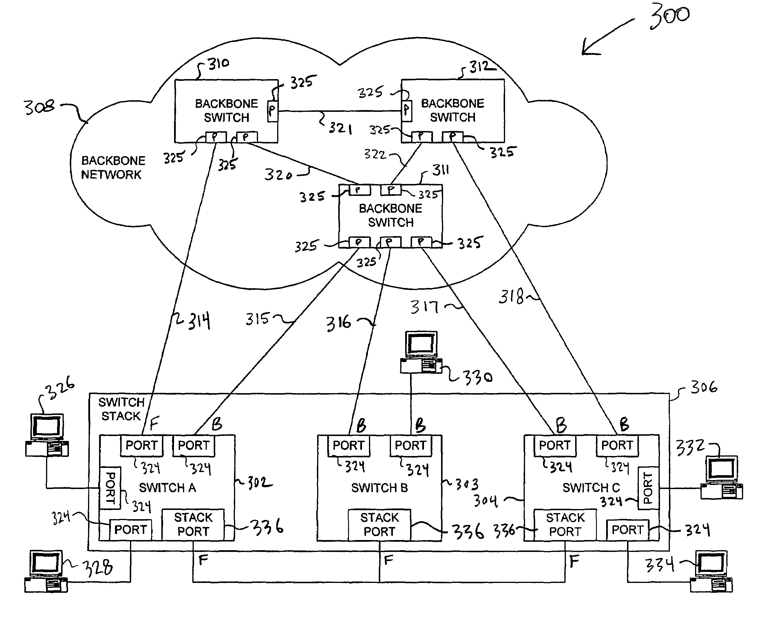
[0047]FIG. 3 is a highly schematic illustration of a bridged network 300. The bridged network 300 includes a plurality, e.g., three, intermediate network devices 302-304 that are organized as a stack 306. In the illustrative embodiment, the network devices 302-304 are network switches and the stack 306 is a switch stack. Bridged network 300 further includes a backbone network 308 which, in turn, includes a plurality of interconnected intermediate network devices, such as backbone switches 310-312. Each switch of switch stack 306 is individually coupled by one or more corresponding ports to the backbone network 308 by corresponds links, such as point-to-point links. Specifically, switch 302 is coupled to backbone switch 310 via link 314, and to backbone switch 311 via link 315. Switch 303 is coupled to backbone switch 311 via link 316. Switch 304 is coupled to backbone switch 311 via link 317, and to backbone switch 312 via link 318. Backbone switches 310-312 are interconnected by a ...


PUM


Abstract

A cross stack rapid transition protocol is provided for permitting multiple network devices organized as a stack to rapidly transition their ports in response to network changes so as to minimize traffic flow disruptions while avoiding loops. Each switch in the stack has a stack port that connects the switch to another switch in the stack, and a plurality of ports for connecting the switch to other entities of the computer network. Each switch includes a Spanning Tree Protocol (STP) entity that transitions the ports of the switch among a plurality of states including a forwarding state and a blocking state. Each switch also tracks which other switches are members of the switch stack. The stack port of each switch is transitioned to the forwarding state, and a single switch having connectivity to a root is elected to be a Stack Root. One or more other switches may have Alternate Stack Root Ports, that provide alternate paths to the root. If the current Stack Root loses connectivity to the root, the switch whose Alternate Stack Root Port represents the next best path to the root issues one or more proposal messages to the other members of the switch stack. These other members respond with an Acknowledgement, and the former Stack Root transitions its port to the blocking state. Once the proposing switch receives an Acknowledgment from all other active members of the switch stack, it transitions its Alternate Stack Root Port to the forwarding state so that network messages can be forwarded to and from switch stack.

Description

BACKGROUND OF THE INVENTION[0001]1. Field of the Invention[0002]This invention relates to computer networks and, more specifically, to reconfiguring a computer network.[0003]2. Background Information[0004]Many organizations, including businesses, governments and educational institutions, utilize computer networks so that employees and others may share and exchange information and / or resources. A computer network typically comprises a plurality of entities interconnected by means of one or more communications media. An entity may consist of any device, such as a computer, that “sources” (i.e., transmits) or “sinks” (i.e., receives) data frames over the communications media. A common type of computer network is a local area network (“LAN”) which typically refers to a privately owned network within a single building or campus. LANs typically employ a data communication is protocol (LAN standard), such as Ethernet, FDDI, Wireless Fidelity (Wi-Fi) or token ring that defines the functions...

Claims


Application Information

Patent Timeline
Patent Type & Authority Patents(United States)
IPC IPC(8): H04L12/28
CPCH04L45/00H04L45/48H04L45/76
Inventor SHUEN, PAULINECHAOU, CHINYINGPADAVALA, MALLIKARJUNA R.PANDE, MONIKALUVE, SHYAMASUNDAR S.
Owner CISCO TECH INC
Why Eureka
Try Eureka