Method and apparatus for estimating channel response and receiver apparatus using the estimated channel response for OFDM radio communication systems
a radio communication system and receiver technology, applied in the field of method and apparatus for estimating channel response and receiver apparatus using the estimated channel response for ofdm radio communication system, can solve problems such as degraded time-domain resolution, and achieve the effect of high accuracy
- Summary
- Abstract
- Description
- Claims
- Application Information
AI Technical Summary
Benefits of technology
Problems solved by technology
Method used
Image
Examples
first embodiment
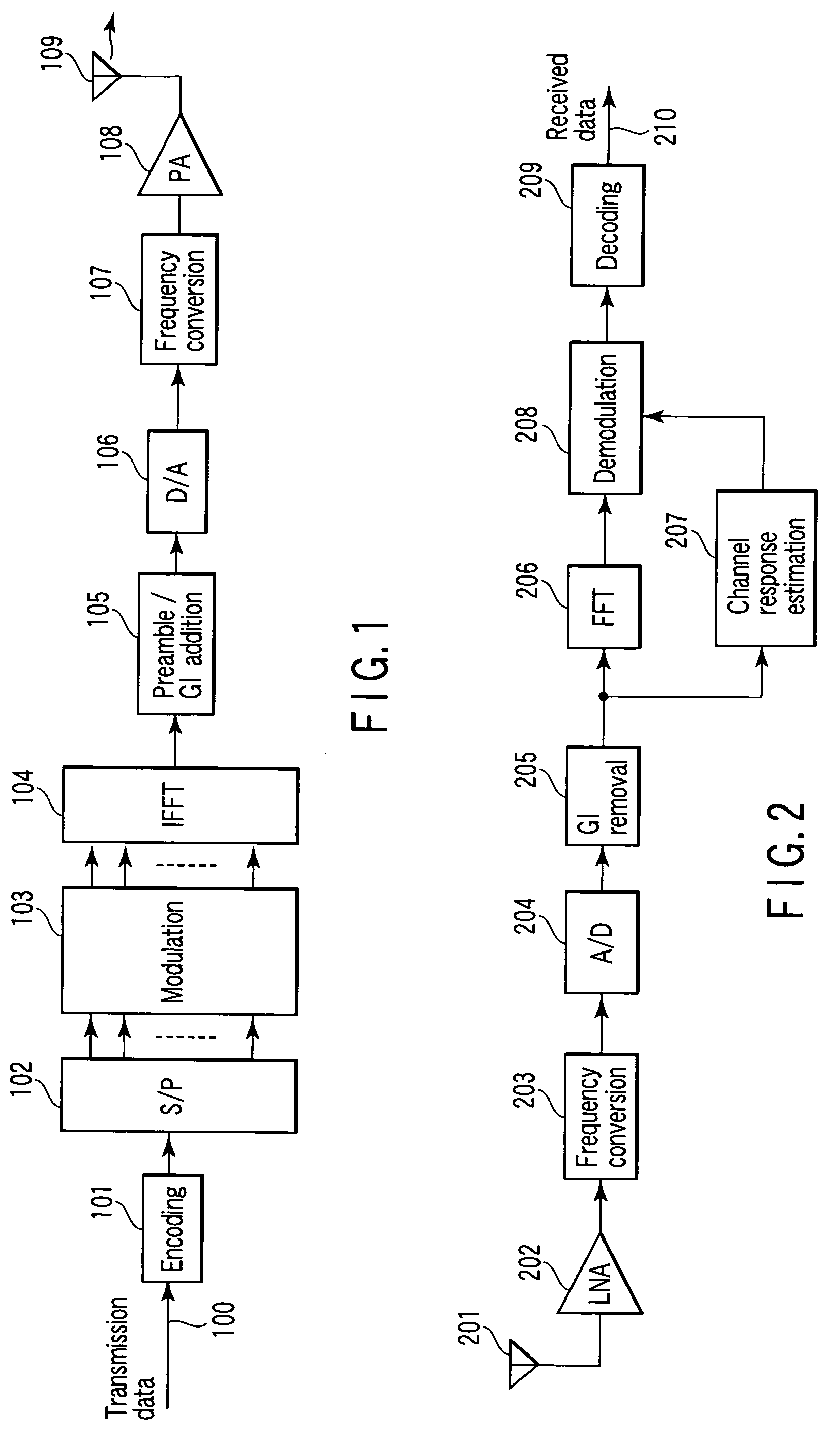
[0026]Referring first to FIGS. 1 and 2, an OFDM radio communication system according to the present invention will be described. As seen from FIG. 1, in an OFDM transmitter included in the system, an encoder 101 subjects transmission data 100 to error correction encoding. The resultant encoded data is sent to a serial / parallel (S / P) converter 102, where it is divided into signals corresponding to the respective subcarriers of an OFDM signal. The resultant signals are input to a modulator 103, where they are subjected to digital modulation such as binary phase shift keying (BPSK).
[0027]The modulated signals are sent to an inverse fast Fourier transformer (IFFT) 104, where they are transformed into a time-domain signal by inverse fast Fourier transform. The output signal of the inverse fast Fourier transformer 104 is sent to a preamble / GI adder 105, where a preamble signal and guard interval (GI) are added to the signal. After that, the resultant signal is sent to a digital-to-analog ...
second embodiment
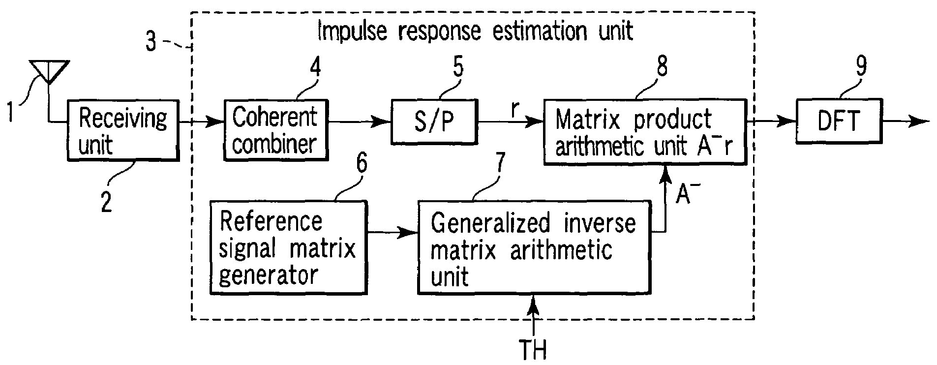
[0060]As shown in FIG. 9, a second embodiment of the invention employs a threshold value setting unit 10 and CNR measuring unit 11 in addition to the channel response estimation unit shown in FIG. 6. The CNR measuring unit 11 measures the carrier -to noise ratio (CNR) of a received signal output from the receiving unit 2. Since a known method is utilized to measure the CNR, no detailed description will be given of the CNR measurement. The measured CNR is sent to the threshold value setting unit 10, which sets threshold value TH used in the generalized inverse matrix arithmetic unit 7, based on the measure CNR.
[0061]As described previously, degradation of the estimation accuracy of the transfer function can be prevented by acquiring a generalized inverse matrix, instead of using singular values not higher than threshold value TH, and singular vectors corresponding to the singular values. The optimal threshold value TH depends upon CNR. For instance, if threshold value TH is set too m...
third embodiment
[0063]As seen from FIG. 10, in a third embodiment of the invention, the channel response estimation unit employs an MCS estimation unit 12 instead of the CNR measuring unit 11 shown in FIG. 9. The MCS estimation unit 12 estimates a modulation and coding scheme (MCS) employed for radio communication, based on a received signal output from the receiving unit 2. In accordance with the estimated MCS, the threshold value setting unit 10 sets threshold value TH used by the generalized inverse matrix arithmetic unit 7.
[0064]In general, in a system that performs communication with MCS appropriately varied, different CNRs are employed between different MCSs. For example, a modulation scheme that uses s large multi-value modulation number is used in an environment in which CNR is high, while a modulation scheme that uses a small multi-value modulation number is used in an environment in which CNR is low. The same can be said of an encoding scheme. An encoding scheme of a high encoding rate is...
PUM
 Abstract
Description
Claims
Application Information
 - R&D
- Intellectual Property
- Life Sciences
- Materials
- Tech Scout
- Unparalleled Data Quality
- Higher Quality Content
- 60% Fewer Hallucinations
Browse by: Latest US Patents, China's latest patents, Technical Efficacy Thesaurus, Application Domain, Technology Topic, Popular Technical Reports.
© 2025 PatSnap. All rights reserved.Legal|Privacy policy|Modern Slavery Act Transparency Statement|Sitemap|About US| Contact US: help@patsnap.com


