Method of producing hard disk drives of reduced size

a technology of hard disk drives and small hdds, which is applied in the manufacture of stator/rotor bodies, mounting heads within housings, instruments, etc., can solve the problems of difficult to produce small hdds, high requirements for mechanical performance of hdds, and restricted use of hdds to store information in computer systems

Inactive Publication Date: 2009-01-27
SONY CORP
View PDF6 Cites 10 Cited by
  • Summary
  • Abstract
  • Description
  • Claims
  • Application Information

AI Technical Summary

Benefits of technology

[0006]Since the spindle motor is a MEMS device, the HDD system is smaller than a conventional HDD system. This makes the present HDD system very suitable for use in portable appliances such as PDAs and cellular phones.
[0012]We have found that the embodiments of the present invention may be able to provide a recording density of over 31 gigabits / cm2 (200 gigabits per square inch), when used with other HDD relates technologies which are emerging.

Problems solved by technology

So far, however, the usage of HDDs has been restricted to storing information in computer systems, rather than in smaller items of consumer electronics.
Recently, with increasing demand for portable consumer products, such as PDAs and cellular phones, there has been an increasing need for a small HDD, but it is difficult to produce small HDDs by applying conventional production methods such as precision machining and assembly techniques because there are difficulties in producing smaller parts and assembling them.
In addition, the requirements for the mechanical performance of an HDD are highly demanding, because high reliability is required of a HDD system.

Method used


Image

  • Method of producing hard disk drives of reduced size
  • Method of producing hard disk drives of reduced size
  • Method of producing hard disk drives of reduced size

Examples


second embodiment

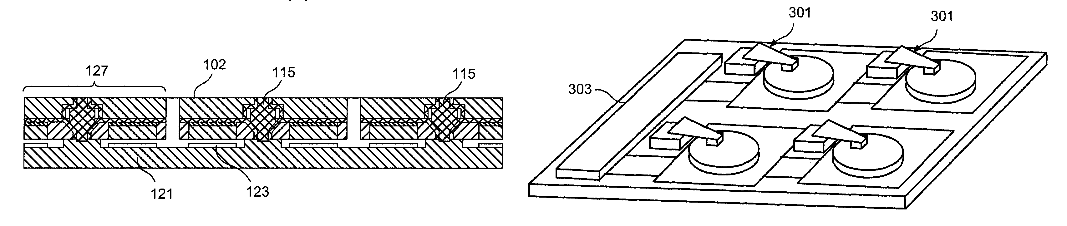
[0052]Turning to FIG. 11, the steps of a method which is the invention are shown. The method employs a substrate 101 which carries a magnetic film 102 which is suitable for data recording. The substrate 101 is used with a second Si substrate 103. As shown in FIG. 11(a), the two Si substrates 101, 103 are each shaped by a deep RIE (reactive ion etching) process to include respective sets of cavities 105, 107. Subsequently a DLC layer 109, 111 is formed on the substrates by implantation.

[0053]As shown in FIG. 11(b), the wafers 101, 103 are then bonded together by a wafer bonding step, so that pairs of the cavities 105, 107 form chambers 113, which each enclose a shaft 115, and cavities 117 are formed in the substrate 103 by plasma etching. The cavities 117 encircle the shafts 115. As shown in FIG. 11(c), circular magnets 119 are formed by electroplating, filling the cavities 117.

[0054]FIG. 11(d) shows a stator substrate 121, which, similarly to the substrate 39 described above, has th...

first embodiment

[0056]At this point, the substrates 101, 103 are cut along lines which are vertical in FIG. 10(e) to isolate individual rotors 127, each comprising a respective shaft 115. The rotors 127 are circular as viewed from the direction along the shafts 115, which is how they are viewed in FIG. 11(f). The rotors 127 each carry a layer 102 of magnetic material on their top surfaces (i.e. their surfaces away from the stator substrate 121), since this was present on the top surface of the substrate 101. Thus, no separate substrate corresponding to the substrate 2 of the first embodiment is required.

[0057]The reason why Si substrates are preferred in the first and second embodiments of the invention is that their surface can be made to be very smooth, and smoothness required in order to be able to form a high performance from a magnetic film deposited on the surface of the Si in later steps of the embodiment. Furthermore, MEMS processes for Si such as etching and wafer bonding techniques have b...


PUM

PropertyMeasurementUnit
total heightaaaaaaaaaa
air pressureaaaaaaaaaa

Abstract

A method of producing hard disk drives of reduced size including using a one or more MEMS spindle motors, and one or more magnetic heads. Each spindle motor includes a rotor and a stator. The rotor carries a film of magnetic film, and a head is arranged to communicate data with the magnetic film. The rotors are formed by MEMS technology. Rotor elements are formed within a substrate 4, and the substrate is subsequently cut to simulate the rotor elements, and turn them into rotors.

Description

FIELD OF THE INVENTION[0001]The present invention relates to hard disk drives (HDDs), to methods for fabricating HDDs, and to portable electronic devices including HDDs.BACKGROUND OF INVENTION[0002]Most modern computers employ data storage systems including hard disk drives (HDDs)—that is systems in which an inflexible disk including magnetic material stores data which is written / read by a magnetic head which moves over the surface of the disk but does not come into physical contact with the disk. Hard disk drives provide high capability for storing information, and over the years, the data storage capacity of HDDs has been increased by several technological innovations, such as the use of GMR (Giant Magneto-Resistive) heads and fluid bearing type spindle motors. So far, however, the usage of HDDs has been restricted to storing information in computer systems, rather than in smaller items of consumer electronics. Recently, with increasing demand for portable consumer products, such ...

Claims


Application Information

Patent Timeline
Patent Type & Authority Patents(United States)
IPC IPC(8): G11B5/105G11B19/20G11B25/04G11B33/12
CPCG11B19/2009G11B25/043G11B33/121Y10T29/49025Y10T29/49009Y10T29/49027Y10T29/49012Y10T29/49023
Inventor TAKADA, AKIOYEO, CHING BIINGOKADA, KANZOKAYAMA, SHUN
Owner SONY CORP
Why Eureka
Try Eureka