Eureka AIR delivers breakthrough ideas for toughest innovation challenges, trusted by R&D personnel around the world.

Radial piston pump

Inactive Publication Date: 2009-01-27
ZF FRIEDRICHSHAFEN AG
View PDF13 Cites 5 Cited by
  • Summary
  • Abstract
  • Description
  • Claims
  • Application Information

AI Technical Summary

Benefits of technology

[0014]The purpose of the present invention is accordingly, to create a radial piston pump with a slip ring assembly so conceived, that an imbalance caused by the slip ring assembly and transferred by the radial piston pump to the transmission and thereafter to the vehicle, is substantially reduced, so that the vibrations are diminished and brought to an uncritical level.

Problems solved by technology

The impacts are particularly severe if, during operation with volute spring activated inlet and outlet valves, suddenly spaces are made available which exhibit large pressure differentials.
If the pressure in the cylinder falls below the closure pressure of the spring loaded valve, then this valve impacts once again on the seat and causes thereby a loud hammering noise.
Also influencing the said hammering noise are the related opening pressures and closing pressures and as well, the rate of increase of pressure at the instant of opening generates noise.
The pressure impacts of all pistons produce a general noise, which resounding from the body of the pump, radiates as audible air-borne noise.
First, the damping characteristic of these rings, which, for instance, generates itself from the elasticity of their construction, reduces the pressure increase gradient in an individual cylinder, which is the cause for the objectionable noise and pulsation development.
The conventional slip ring assembly for radial piston pumps, as it is applied generally for a continuous and automatic transmission, i.e., the so-called CFT-transmission, still exhibits the disadvantage of considerable weight, so that this causes an imbalance in the gear train and leads to vibrations of the transmission.

Method used


Image

  • Radial piston pump
  • Radial piston pump
  • Radial piston pump

Examples


Embodiment Construction

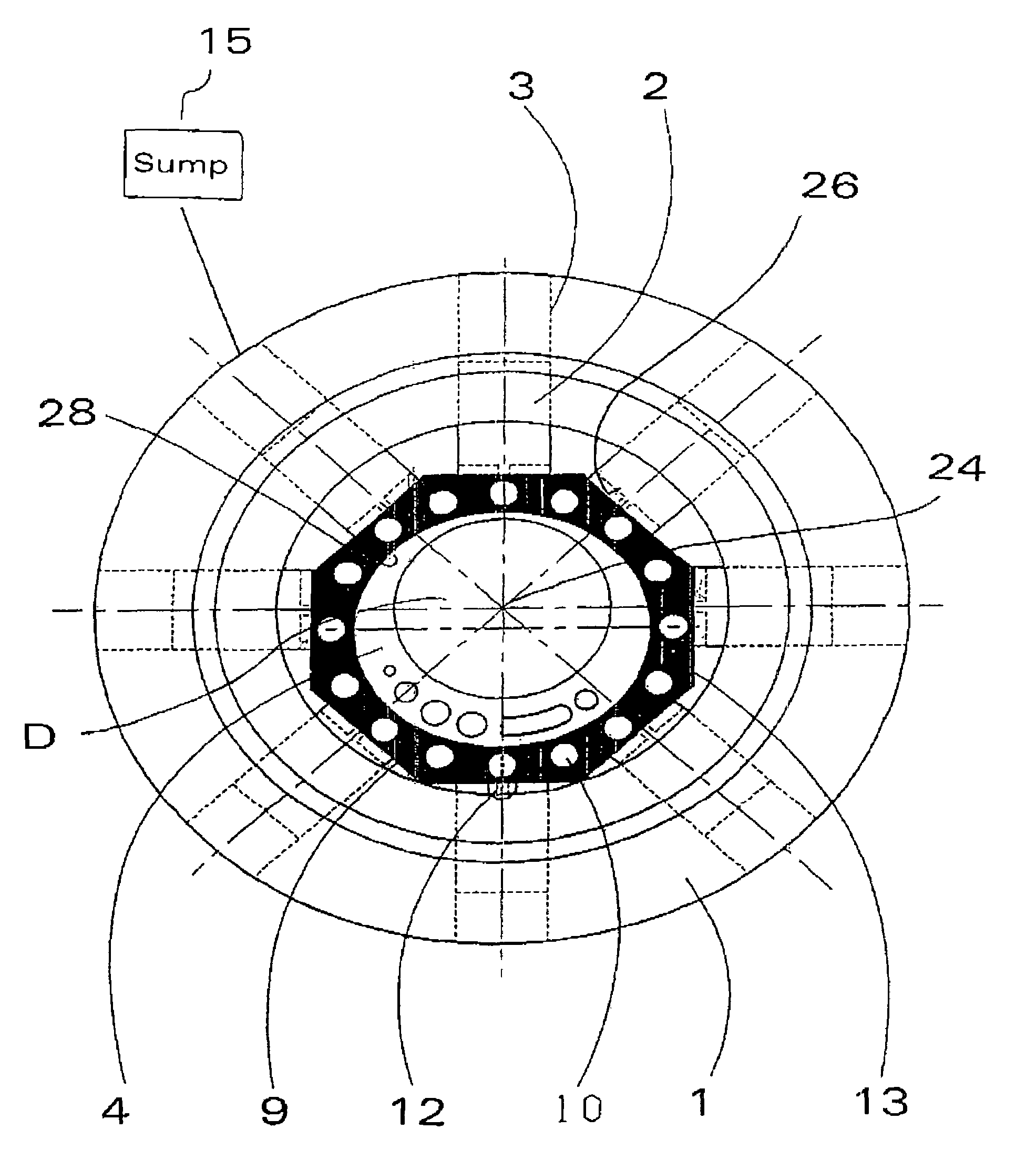
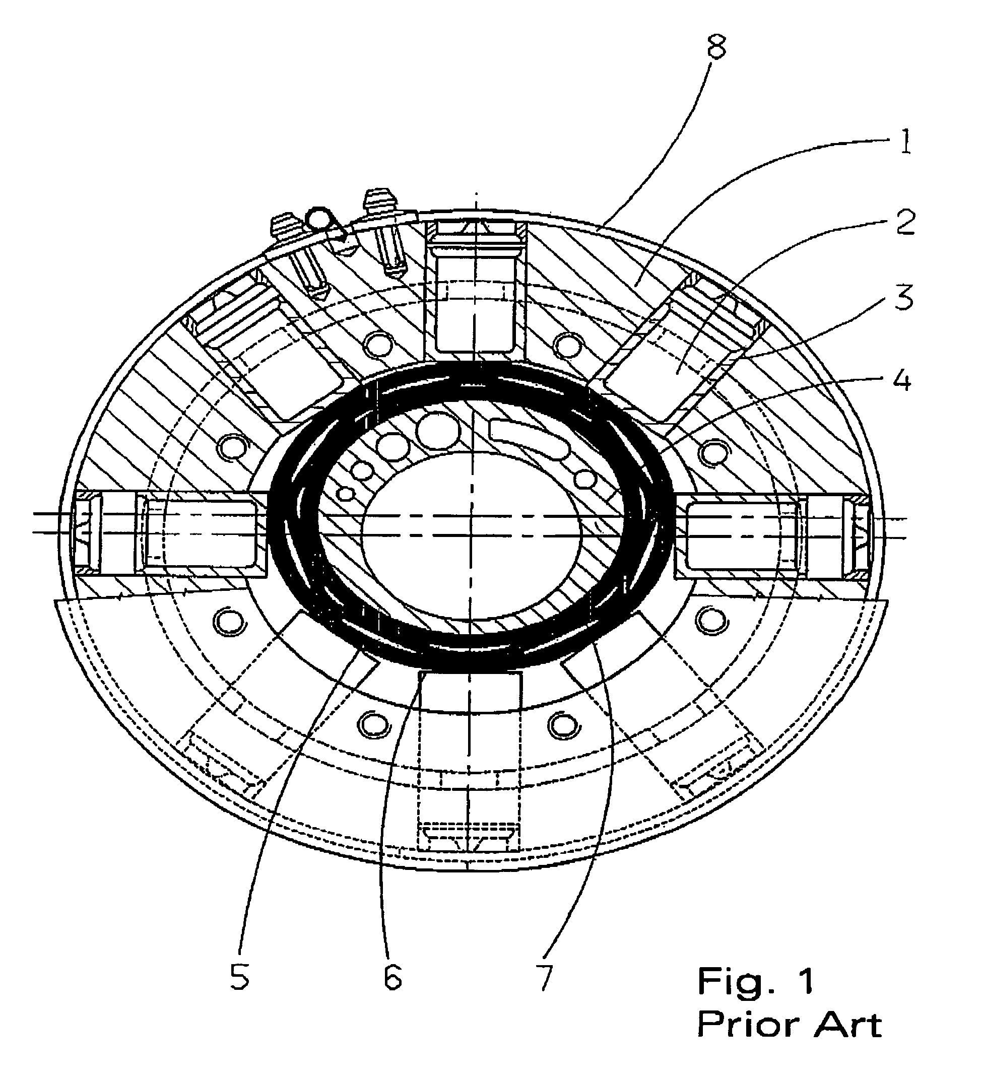
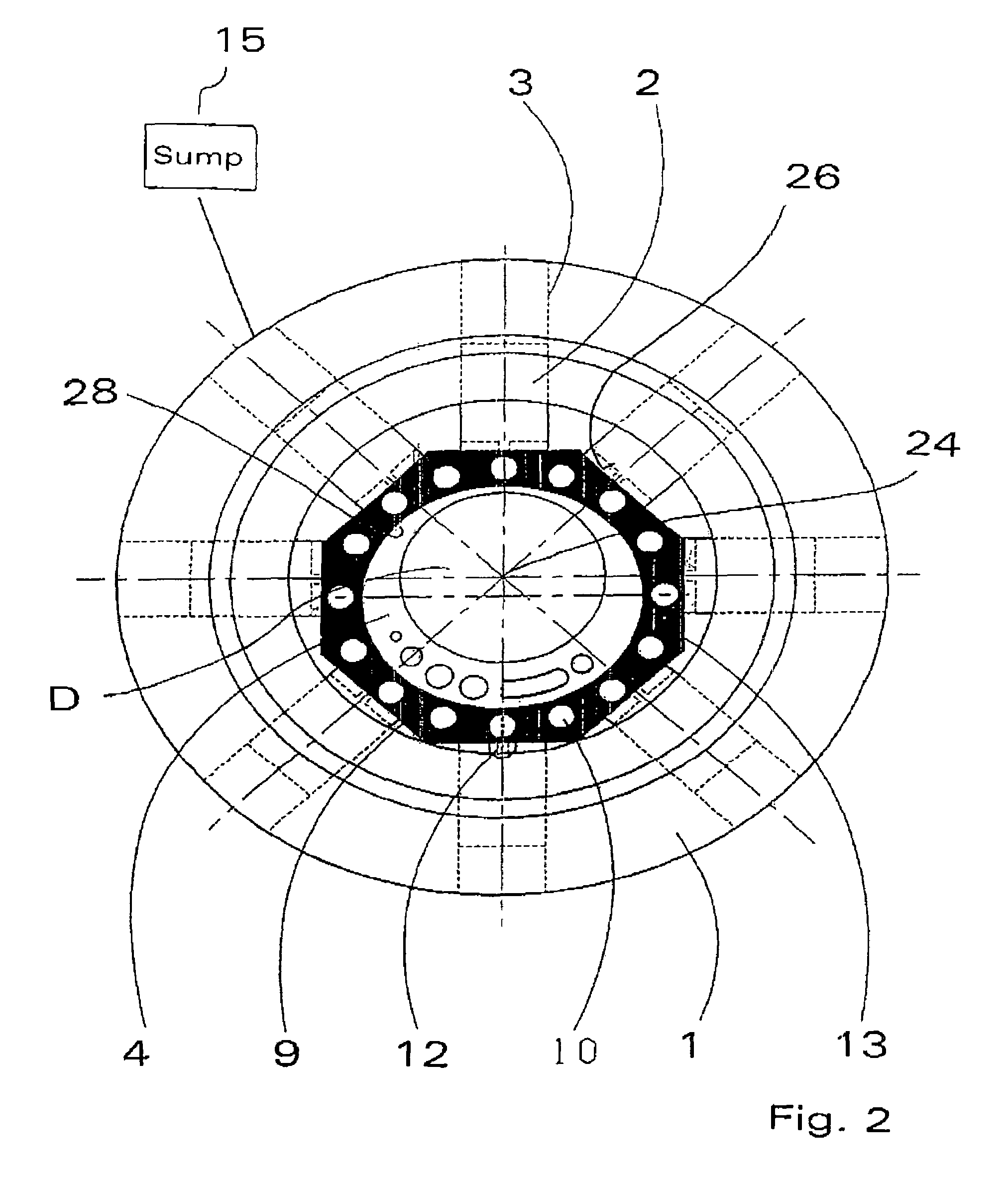
[0035]The pump body is designated by the reference number 1, in which said body a plurality of cylinders 3 are placed, and in the said cylinders 3 are respectively located pistons 2. Each piston 2 is loaded by a spring, which abuts itself against a stopper. A spring 8, in ring shape, encloses all stoppers and closes outlet borings to inner spaces leading to a collecting annular groove. The ring spring, in this way, forms a check valve for each cylinder.

[0036]In this conventional radial piston pump, an eccentric 4 is mounted upon a drive shaft D, whereby the driven eccentric 4 is surrounded by a slip ring assembly 5, 6 and 7. The said assembly comprises an inner ring 6, and outer ring 5 and a ring spring 7 interposed between the two inner and outer rings.

[0037]During the rotation of the driven eccentric 4, those respective pistons 2 which are expelling the pressurized oil, to a small extent, can resiliently press against the outer ring 5, so that, at the start of a pressure thrust, o...


PUM


Abstract

Proposed is a radial piston pump with a pump body, in which pistons and cylinders are circumferentially arranged about a driven eccentric, which the pump possesses a faceted slip ring (9) assembly which has an inner diameter and a polygonal outer diameter, the polygon consists of straight, axial parallel surfaces (13), the number of which represents the number of pistons (2) contained in the radial piston pump.

Description

[0001]This application claims priority from German Application Ser. No. 103 47 715.2 filed Oct. 14, 2003.FIELD OF THE INVENTION[0002]The present invention concerns a radial piston pump, with a pump body, in which piston and cylinders are radially placed about a driven eccentric.BACKGROUND OF THE INVENTION[0003]Radial piston pumps have been extensively used in motor vehicles for transporting lubricating oil, pumping fuel, and as pressure generating means for hydraulically operated servomechanisms. Such pumps find further use as hydraulic pumps for power steering, shock absorbers, clutches and continuous transmissions, automatically controlled transmissions, and hydraulically operated driving and auxiliary equipment, and for operational machines and the like. Radial piston pumps are predominately installed in cases where a higher hydraulic pressure level is necessary.[0004]Serving as pumps of the displacement type, radial piston pumps do not deliver a pumped medium in continuous flow,...

Claims


Application Information

Patent Timeline
IPC IPC(8): F04B1/04F01B1/00F04B39/10F04B9/04
CPCF04B1/0413F04B9/045
Inventor WINTER, JENS
Owner ZF FRIEDRICHSHAFEN AG
Why Eureka
Eureka Blog
Learn More