Fan rack fixture having two pairs of positioning and locking portions

a technology of positioning and locking portions and fan racks, which is applied in the direction of electric apparatus casings/cabinets/drawers, piston pumps, instruments, etc., can solve the problems of long assembling and disassembly process, inconvenient use of tools, and structure of fixing components and other fixing components, so as to achieve fast and convenient assembling and disassembly, and the effect of integral width of the server

Inactive Publication Date: 2009-01-27
INVENTEC CORP
View PDF6 Cites 30 Cited by
  • Summary
  • Abstract
  • Description
  • Claims
  • Application Information

AI Technical Summary

Benefits of technology

[0012]Accordingly, it is a primary objective of the present invention to solve the drawbacks of the aforementioned conventional technology by providing a fan rack fixture, which is capable of assembling / disassembling a fan rack to / from a housing of an electronic device even without any tool.
[0013]It is another objective of the present invention to provide a fan rack fixture, which is capable of assembling / disassembling the fan rack to / from the housing of the electronic device quickly and conveniently.
[0017]Applications of the present invention can assemble and disassemble quickly and conveniently merely by using simply operation, thereby solving the drawbacks, such that additional tools are required employing to lock or withdraw screws, which makes the assembling and disassembling process waste long time, during the assembling process, it tends to affect by the circumstance and cause that the screws are dropped to the inner of the server housing or lost, thereby resulting in the process for assembling and disassembling inconveniently and slowly, in the conventional technology.
[0018]Moreover, the present invention can be applied in fan rack, electronic device and its housing with the existing specifications, thereby avoiding the problems, such that in order to maintain setting space and the corresponding number for the power supply, the integral width of the server must be increased, which departs from the developing trend for miniaturization of various electronic devices, and due to the addition of width, it can not be applied in a machine cabinet or modular machine room with general specifications, universality of the product is relatively deduced, in the conventional technology. Furthermore, the present invention can be applied in fan rack, electronic device and housing with the existing and new specifications, it has much more spring in design.
[0019]As described above, the fan rack fixture according to the present invention can assemble and disassemble quickly and conveniently without tools, so as to solve various drawbacks of the conventional technology, which makes the present invention have significantly high value in use of the industry.

Problems solved by technology

Although the above patent has provided the assembling and disassembling design for the fixing base, structures of the fixing component and the other fixing component are too complex, and aligning steps for assembly are also not easy, specially, the inner of the server housing are full of many setting components and layouts, it is quite difficult and inconvenient to disassemble and assemble whether using tools or not in the limited space of the inner of the server housing, thus, it is needed improving.
In addition, if the above-discussed fixing component is changed to the screw locking design, additional tools are required employing to lock or withdraw the screws when assembling or disassembling the fixing base, which makes the assembling and disassembling process waste long time, during the assembling process, it tends to affect by the circumstance and cause that the screws are dropped to the inner of the server housing or lost, thereby resulting in the process for assembling and disassembling inconveniently and slowly.

Method used


Image

  • Fan rack fixture having two pairs of positioning and locking portions
  • Fan rack fixture having two pairs of positioning and locking portions
  • Fan rack fixture having two pairs of positioning and locking portions

Examples


Embodiment Construction

[0028]The following illustrative embodiments are provided to illustrate the disclosure of the present invention, these and other advantages and effects can be apparent to those skilled in the art after reading the disclosure of this specification. The present invention can also be performed or applied by other different embodiments. The details of the specification may be on the basis of different points and applications, and numerous modifications and variations can be devised without departing from the spirit of the present invention.

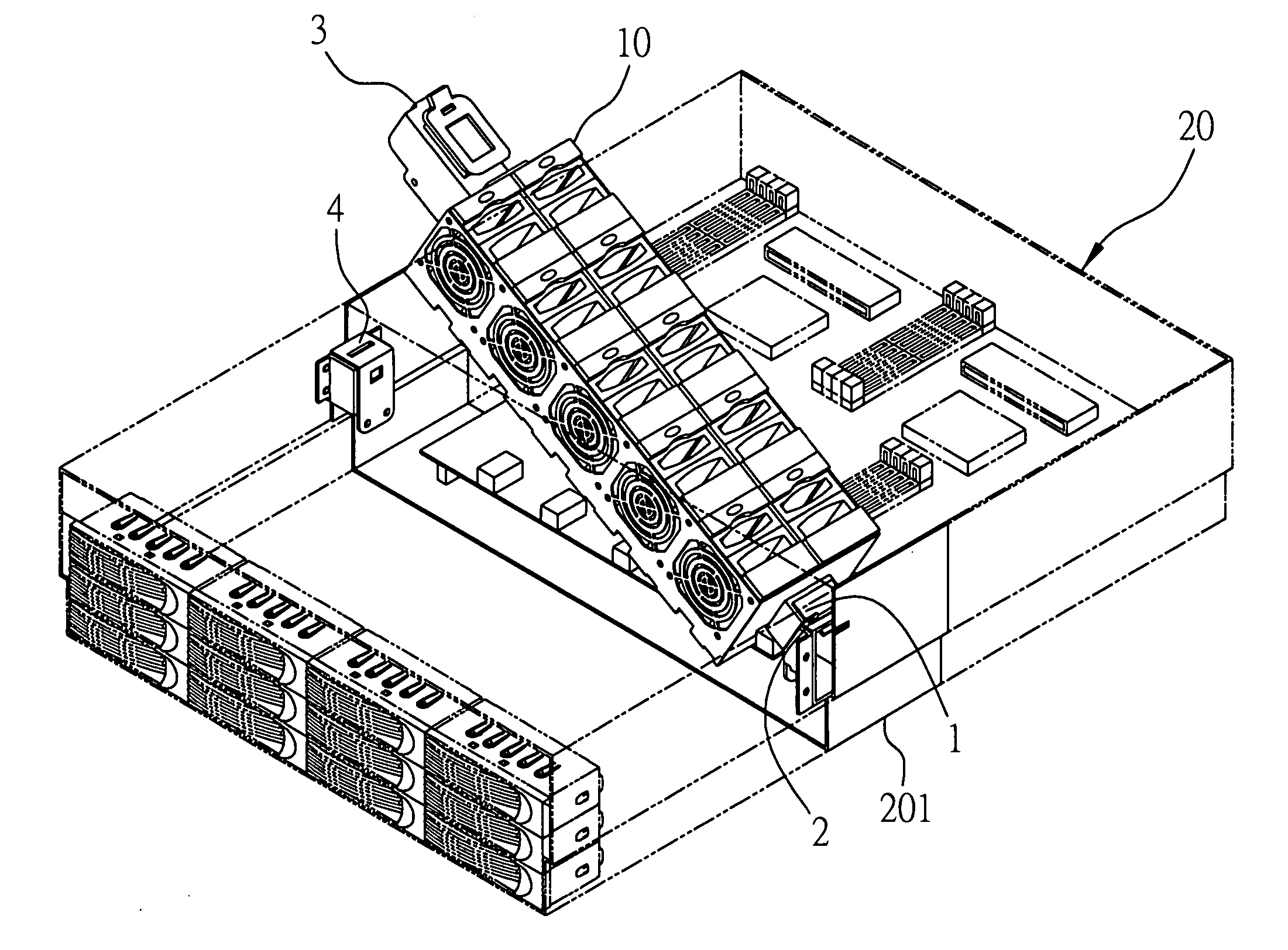
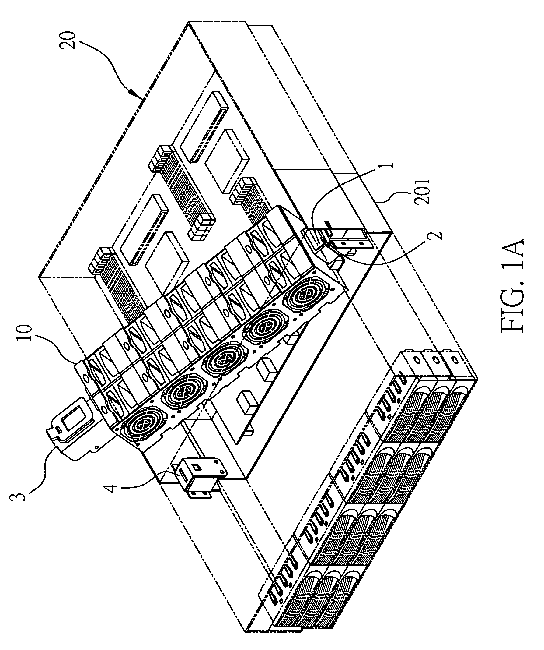
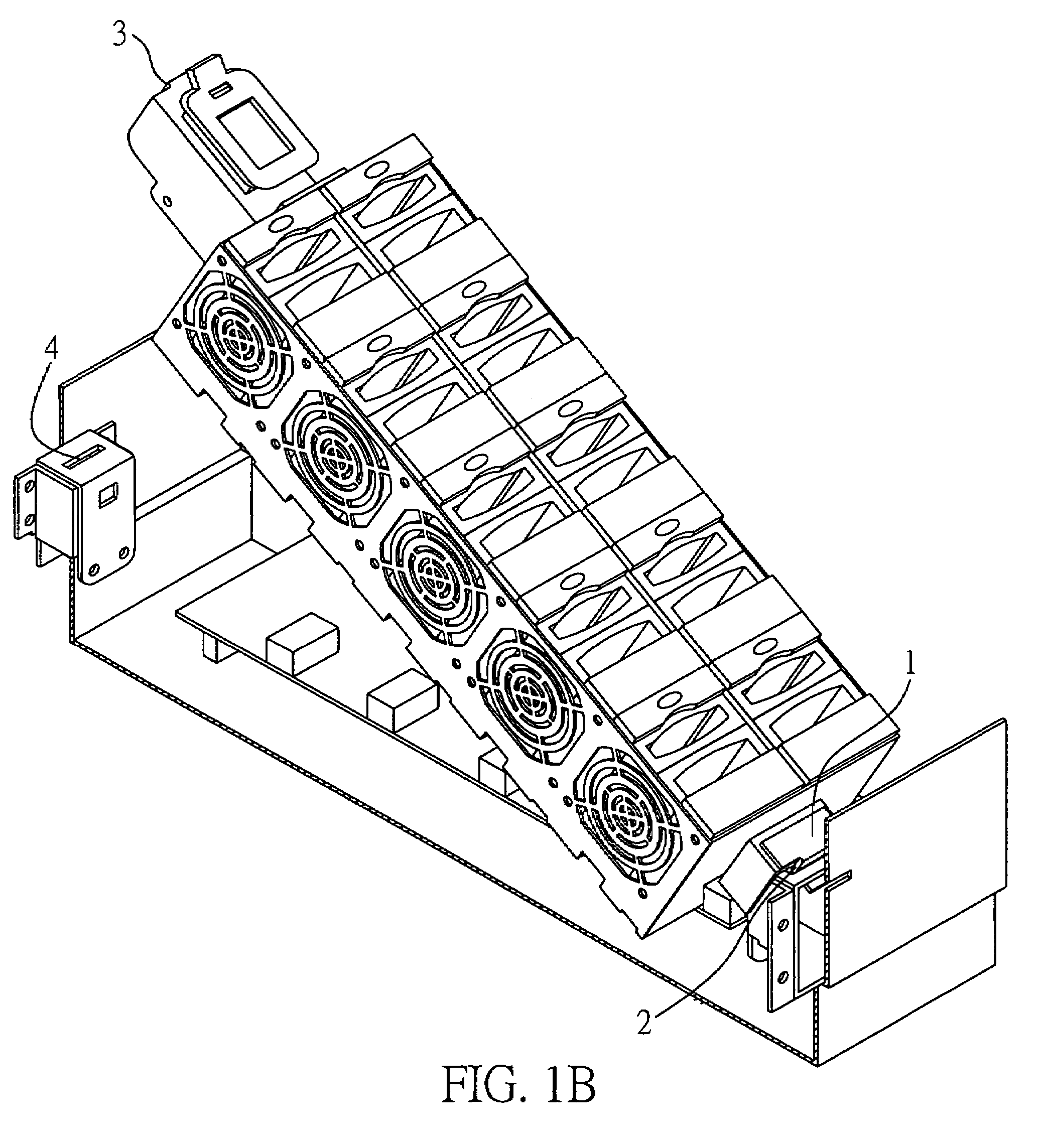
[0029]FIG. 1A is a schematic diagram of a fan rack fixture of the preferred embodiment and a fan rack 10 and an electronic device 20, the fan rack 10 being fixed to a housing 201 of the electronic device 20 by the fan rack fixture, according to the present invention. FIG. 1B is an explosive view of the fan rack fixture and the fan rack 10. As shown in FIG. 1A, the fan rack fixture according to the present invention is used to fix the fan rack 20 to th...


PUM


Abstract

A fan rack fixture for fixing a fan rack to a housing of an electronic device is disclosed. The fan rack fixture includes a first positioning portion installed on a first side of the fan rack, a first locking portion installed on a first side of the housing for fixing the first positioning portion, a second positioning portion installed on a second side of the fan rack and opposite to the first positioning portion, and a second locking portion installed on a second side of the housing for fixing the second positioning portion. By virtue of the fan rack fixture, the fan rack can be assembled / disassembled to / from the housing of the electronic device, even without the use of any tool.

Description

BACKGROUND OF THE INVENTION[0001]1. Field of the Invention[0002]The present invention relates generally to a fan rack, and more particularly, to a fan rack fixture having two pairs of positioning and locking portions for fixing a fan rack to a housing of an electronic device.[0003]2. Description of Related Art[0004]With rapid development of electronic products, people's life is becoming more and more comfortable by such various electronic devices. Specially, computer industry is making an increasing progress with the work frequency, which easily increases the temperature of the electronic components (for example, CPU, hard disk, display card and so on). Therefore, a pocket fan has become one of the most popular heat sinks and has been widely applied in an electronic device, e.g., a computer, a server and the like.[0005]Taken the application in server for example, Taiwan Patent No. 584,264 proposed a heat dissipating configuration for server, which is configured in an inner part of a...

Claims


Application Information

Patent Timeline
Patent Type & Authority Patents(United States)
IPC IPC(8): H05K7/20
CPCF04D25/0613F04D25/166F04D29/601G06F1/20H05K7/20727
Inventor KAO, KUANG-YICHANG, LIN-WEIHSIEH, CHI-KANG
Owner INVENTEC CORP
Why Eureka
Try Eureka