High efficiency amplification

a high efficiency, amplification technology, applied in the direction of electric variable regulation, process and machine control, instruments, etc., can solve the problems of challenging rf problems, low overall efficiency of amplifiers, and general problems of repeatability of such designs in production

Inactive Publication Date: 2009-01-27
SNAPTRACK
View PDF22 Cites 126 Cited by
  • Summary
  • Abstract
  • Description
  • Claims
  • Application Information

AI Technical Summary

Benefits of technology

[0076]The provision of a feedback loop in the supply voltage adjustment block, in accordance with the preferred embodiment of the invention, allows for a fast corrective loop with a wide bandwidth. Similar advantages are obtained for the feedforward case.

Problems solved by technology

As such, the amplifier may exhibit low overall efficiency.
Techniques that vary the device geometry and load tend to be very dependent on the particular power amplifier topology used, and generally present challenging RF problems.
Repeatability of such designs in production is generally a problem.
This technique tends to be generally too demanding upon the supply modulator when using high modulation bandwidths, and thus has limited usefulness in practical applications.
However, in order to operate at full bandwidth, the supply must switch at many times the bandwidth of the modulation, and this excessively high switching speed results in poor modulator efficiency.
This switching creates transient disturbances that degrade the spectrum with high order intermodulation products, and makes linearization difficult by introducing supply dependent non-linearities alongside input dependent non-linearities.
However, there is a problem in achieving this without impact upon tracking speed capability.

Method used


Image

  • High efficiency amplification
  • High efficiency amplification
  • High efficiency amplification

Examples


Embodiment Construction

[0044]The present invention is described herein by way of particular examples and specifically with reference to a preferred embodiment. It will be understood by one skilled in the art that the invention is not limited to the details of the specific embodiments given herein. In particular the invention is described herein by way of reference to an RF amplification stage. However more generally the invention may apply to any arrangement where it is necessary to switch between a plurality of voltage supplies.

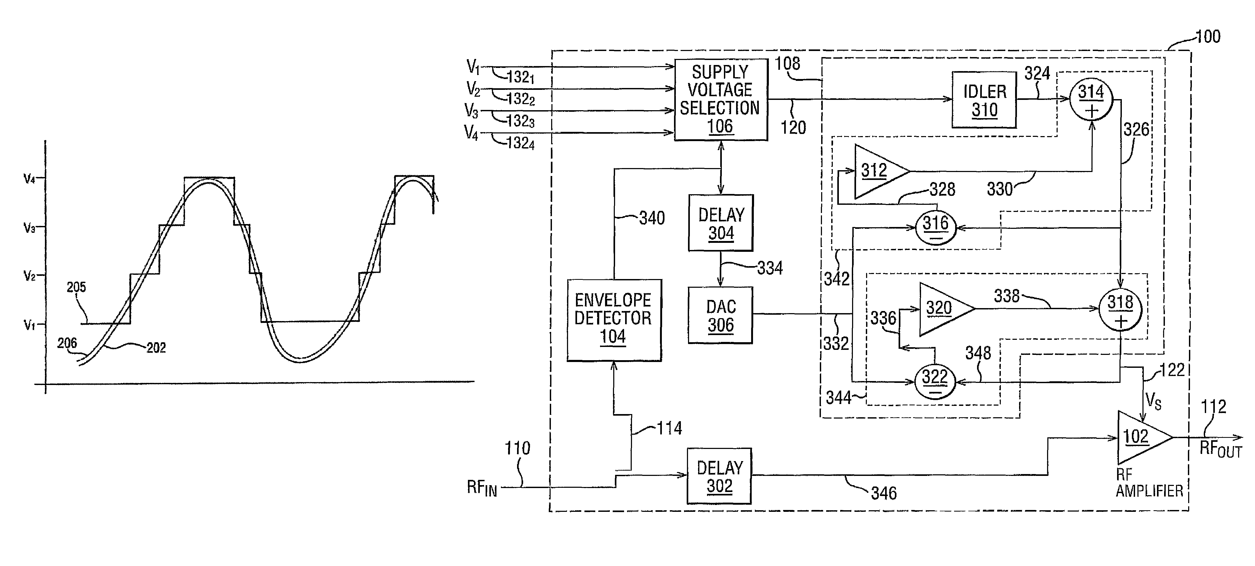
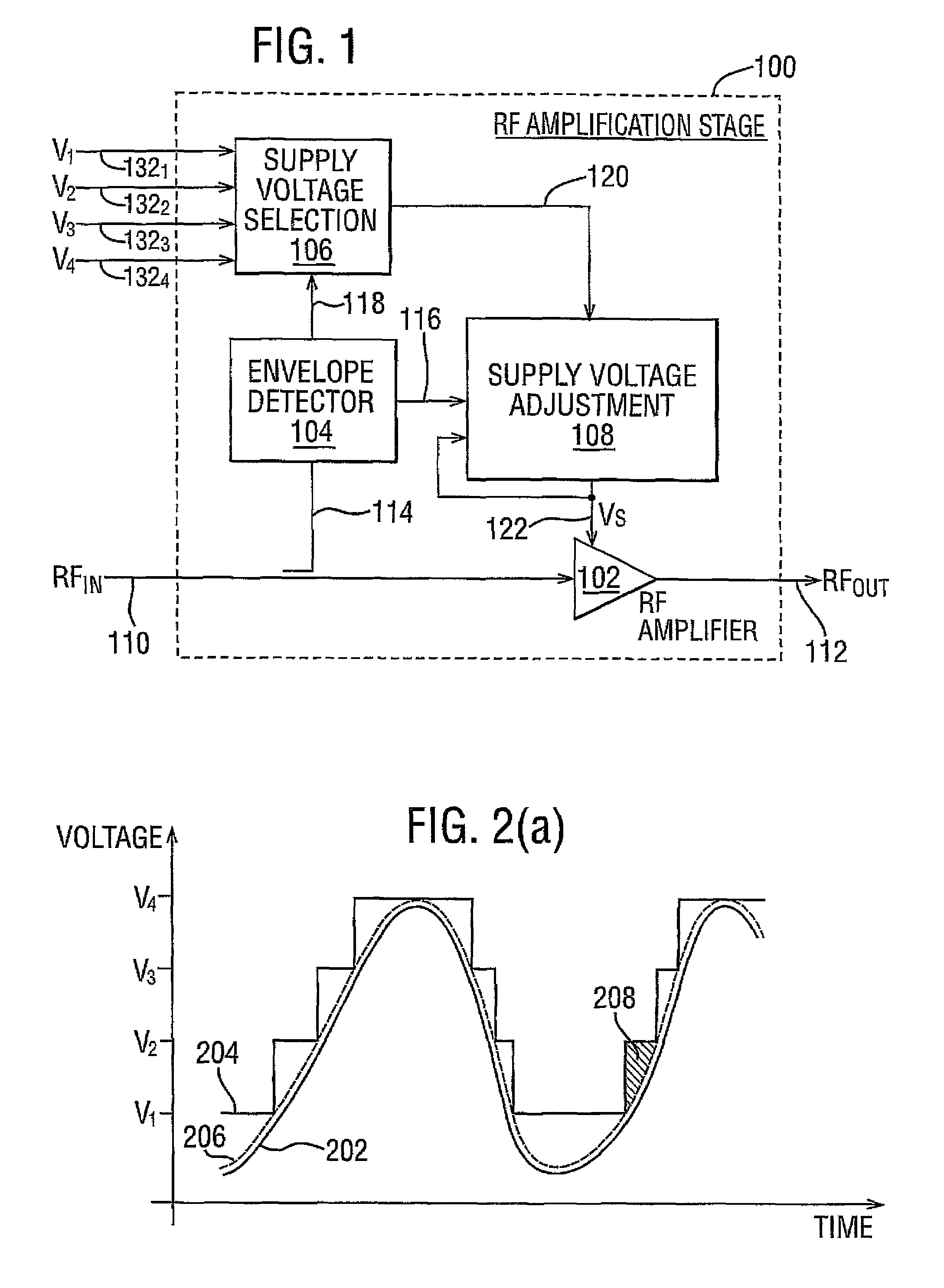
[0045]Referring to FIG. 1, there is illustrated an RF amplification stage 100 in accordance with the general principles of the present invention. The RF amplification stage 100 includes an RF amplifier 102, a supply voltage selection block 106, an envelope detector 104, and a supply voltage adjustment block 108.

[0046]The supply voltage selection block 106 receives four supply voltages V1-V4 on respective input lines 1321-1324. The selected supply voltage is output from the supply ...


PUM


Abstract

A radio frequency amplification stage including an amplifier for receiving an input signal to be amplified and a power supply voltage; and a power supply voltage stage for supplying said power supply voltage, including a circuit for providing a reference signal representing the envelope of the input signal; a circuit for selecting one of a plurality of supply voltage levels in dependence on the reference signal; and a circuit for generating an adjusted selected power supply voltage, including an ac amplifier for amplifying a difference between the reference signal and one of the selected supply voltage level or the adjusted selected supply voltage level, and a summer for summing the amplified difference with the selected supply voltage to thereby generate the adjusted supply voltage.

Description

CROSS-REFERENCE TO RELATED APPLICATIONS[0001]The present application is a National Stage filing under 35 U.S.C. 371 of International Application No. PCT / GB2003 / 004507 filed 17 Oct. 2003 which claims priority to GB Application No. 0303826.2 filed 19 Feb. 2003; the entire disclosures of which are incorporated herein by reference.FIELD OF THE INVENTION[0002]The present invention relates to the control of a supply voltage, in an arrangement in which the supply voltage is selectable. The invention is particularly but not exclusively concerned with the control of a supply voltage to an amplifier such as a broadband radio frequency (RF) amplifier having a wide dynamic range.BACKGROUND TO THE INVENTION[0003]Transistor amplifiers have a peak efficiency for a particular input power that is a function of geometry (i.e. circuit components and layout), load and supply voltage. In conventional radio frequency (RF) power amplification these characteristics are fixed based on the peak input level e...

Claims


Application Information

Patent Timeline
Patent Type & Authority Patents(United States)
IPC IPC(8): H03F1/00H03F1/02
CPCH03F1/025H03F3/21H03F1/0222H03F3/19H03F1/02H03F3/189H03F1/00H03F2200/102H03F2200/331H03F2200/504H03F2200/511H03F2200/451G05F1/46H03F3/245
Inventor WILSON, MARTIN PAUL
Owner SNAPTRACK
Why Eureka
Try Eureka