Eureka AIR delivers breakthrough ideas for toughest innovation challenges, trusted by R&D personnel around the world.

Test rack adapter for hard disk drive

a hard disk drive and adapter technology, applied in the direction of instruments, electrical apparatus casings/cabinets/drawers, instruments, etc., can solve the problems of production costs associated with test rack use and inefficiency of testing

Active Publication Date: 2009-01-27
MAXTOR
View PDF17 Cites 95 Cited by
  • Summary
  • Abstract
  • Description
  • Claims
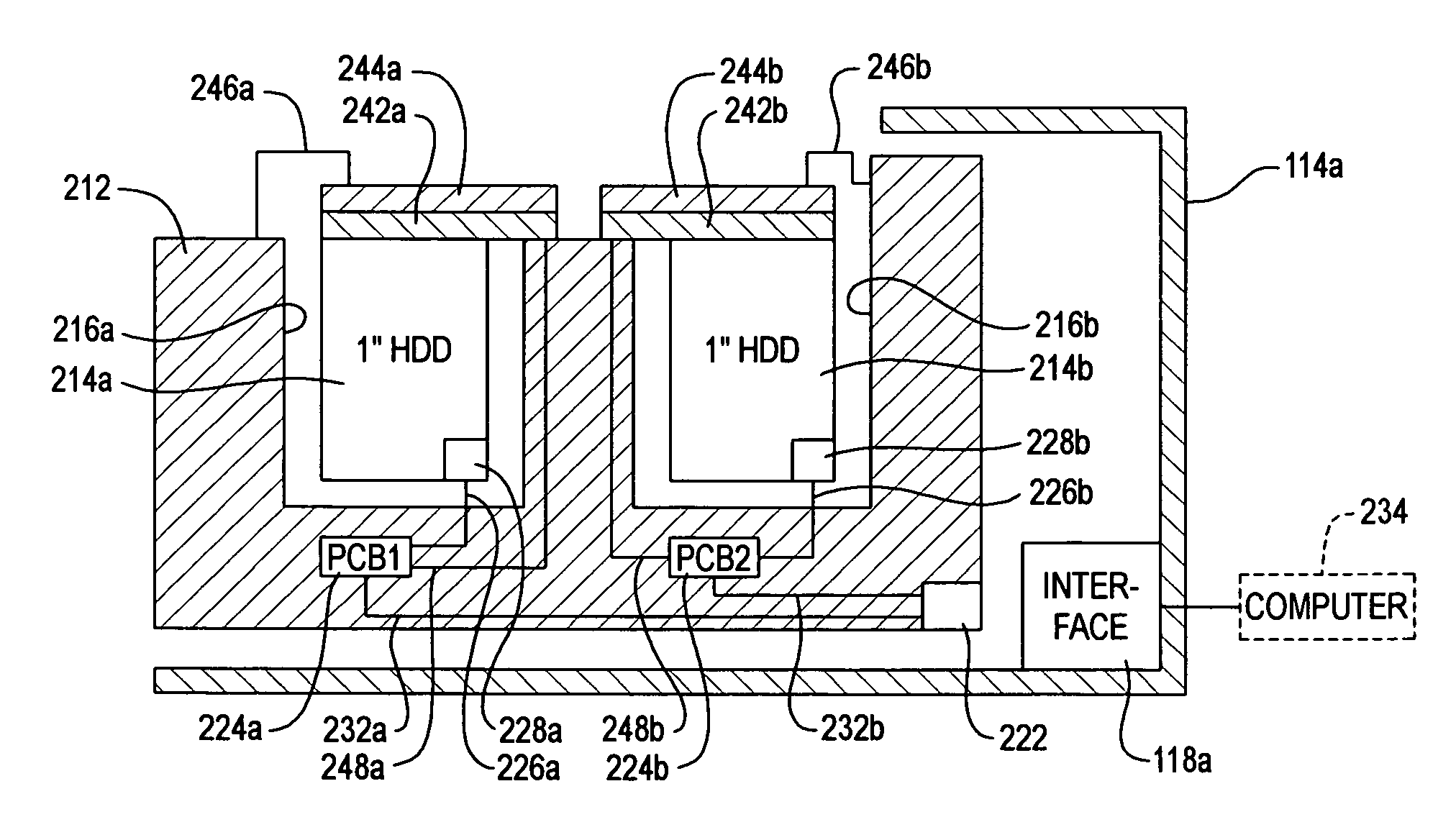
  • Application Information

AI Technical Summary

Benefits of technology

[0009]In general, hard disk drive test racks have slots which are configured to accommodate a particular size, shape and / or form factor of HDD. Many previous (“legacy”) test racks have slots configured to accommodate the common 3½ inch HDD form factor. Thus, it is not surprising that previous test rack slots typically had a single (“native”) electrical interface (e.g., for providing power and / or data or control signals to the HDD) for each slot, which was typically configured and positioned to couple with corresponding power or signal connectors on the HDD. Those skilled in the art will understand the various styles of power, signal and data interfaces and connectors typically used with previous HDDs. Thus, it is possible to define the “slot” of previous racks either as the space configured to accommodate a single HDD of a given form factor or as the space served by a single electrical interface.
[0010]According to one embodiment of the invention, an adapter is provided which allows two or more hard disk drives to simultaneously undergo testing or self-testing procedures while coupled to an adapter which is positioned at least partially within (and / or coupled to) a single test rack slot and / or while receiving power, data or control via a single test rack slot interface. Typically, the HDDs will have a form factor smaller than the form factor for which the test rack slot was designed, such as accommodating two, or more preferably four, or even more preferably six, eight or more, one-inch form factor HDDs in a test rack slot originally designed to accommodate a single 3½ inch HDD.
[0011]Preferably, the adapter is configured to provide at least some degree of individualization of testing such as providing the ability to send different power or control or data signals to, or receive data from, two or more different HDDs in the same test rack slot. The power, control or data sent to or obtained from one of the HDDs in (or coupled to) the slot is typically different, in content and / or timing, from the power, data or control signals sent to or received from at least one other of the HDDs in (or coupled to) the same test rack slot.
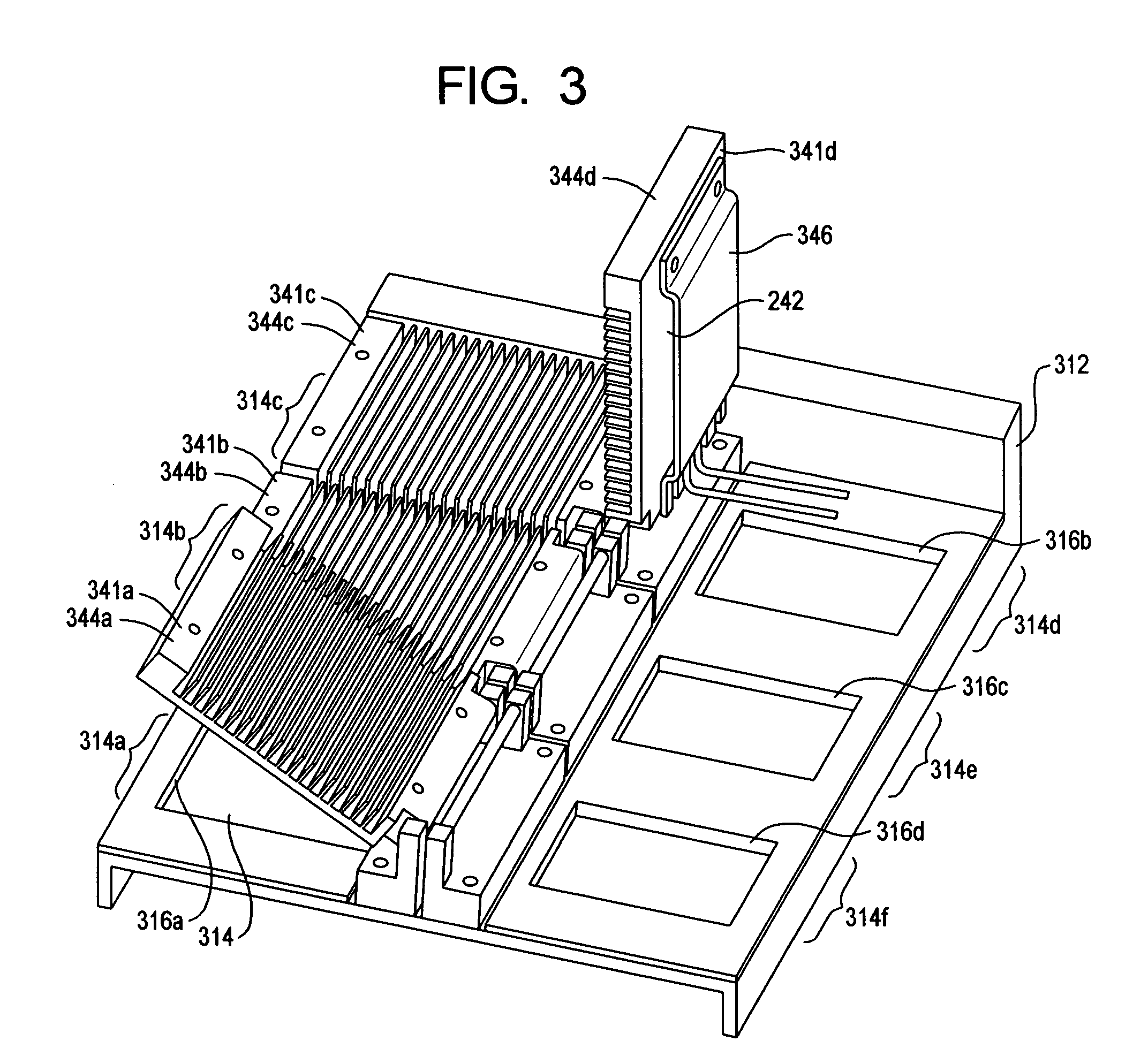
[0012]According to some facets of the invention, the adapter includes one or more electrical circuits, circuit components or circuit boards connected directly or indirectly to the native test rack interface and also connected, directly or indirectly, to two or more HDDs in a single test rack slot. In one embodiment of the invention, the adapter includes, or can be coupled to, HDD-specific cooling or heating devices which can provide two different temperatures for at least first and second HDDs positioned in, or coupled to, a single test rack slot. In one embodiment, the HDD-specific temperature control device includes one or more peltier cells.
[0013]In one embodiment, an adapter which allows two or more hard disk drives to conduct self-testing in a single test rack slot is provided. Testing can be individually controlled for the various HDDs in a slot. Peltier cell devices or other cooling or heating devices can be controlled to achieve individualized temperature control for HDDs in the test rack slot.

Problems solved by technology

The production costs associated with test rack use is also related to the length of time, allocatable to individual HDDs, spent in the test rack, as needed to perform the self-testing.
Many previous systems involve changing the temperature of the entire clean room or other test rack area, leading to testing inefficiencies, e.g., when not all HDDs need to be tested at the same temperature for the same periods of time.
Even if the temperatures within individual test rack slots were independently controlled, there is a potential for inefficiency if temperature control with a granularity smaller than test rack slots is useful.

Method used


Image

  • Test rack adapter for hard disk drive
  • Test rack adapter for hard disk drive
  • Test rack adapter for hard disk drive

Examples


Embodiment Construction

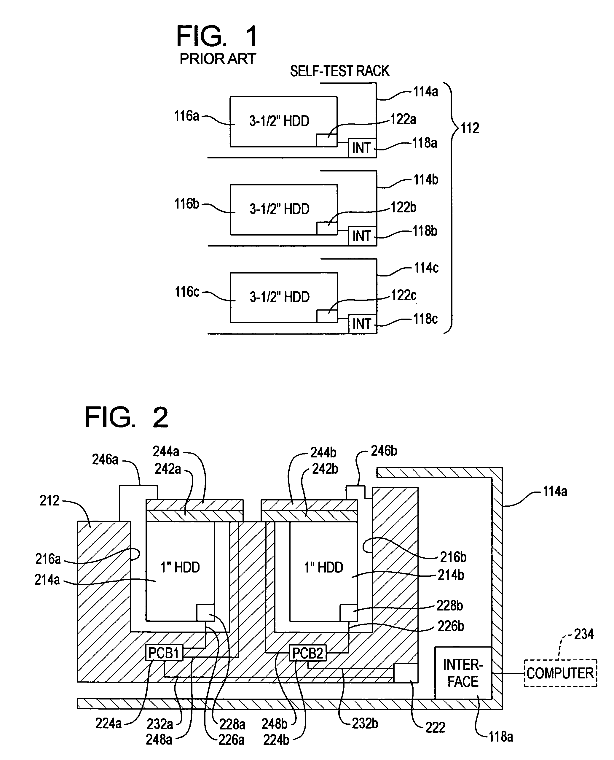
[0019]A typical previous test rack is a rectangular array of rectangularly-shaped slots, each slot having an electrical interface. Those skilled in the art will understand the actual shape and construction of previous test racks. FIG. 1 is not intended to show the actual details of construction of a test rack, but to provide an indication of the relationship of certain components of test racks and HDDs contained therein.

[0020]As illustrated in FIG. 1, in previous devices and approaches, a self-test rack 112 had a plurality of slots 114A, B, C. Each slot 114A, B, C is sized and shaped to accommodate or receive a single HDD of a particular form factor such as an HDD with a 3½ inch form factor 116A, B, C. Each slot 114A, B, C has an electrical interface 118A, B, C, which may be connected to power, control signal or data sources (not shown). Each interface 118A, B, C includes components for coupling to corresponding power, control signal and / or data connectors 122A, B, C of the drives 1...


PUM


Abstract

An adapter which allows two or more hard disk drives to conduct self-testing in a single test rack slot is provided. Testing can be individually controlled for the various HDDs in a slot. Peltier cell devices or other cooling or heating devices can be controlled to achieve individualized temperature control for HDDs in the test rack slot.

Description

CROSS-REFERENCE TO RELATED APPLICATIONS[0001]Priority is claimed from U.S. Provisional Application Ser. No. 60 / 722,831 filed Sep. 30, 2005, which is incorporated herein by reference.FIELD OF THE INVENTION[0002]The present invention is directed to an apparatus, system and method which adapts a hard disk drive (HDD) test rack, configured to normally accommodate, in each of a plurality of slots, at least a first size or style of HDD, such that, following adaptation, one or more of the single-drive slots of the test rack can accommodate two or more HDDs, and preferably provides at least partially-individualized test control and / or data collection.BACKGROUND INFORMATION[0003]Many HDD production facilities and procedures involve performing one or more tests on HDDs, often following, or as part of, the servo track writing (STW) procedure. Such tests can be used for one or more of a number of purposes, including detecting flaws or anomalies, preferably, while obtaining information about the...

Claims


Application Information

Patent Timeline
Patent Type & Authority Patents(United States)
IPC IPC(8): G06F1/16
CPCG06F1/187
Inventor MARVIN, JR., WILLIAM M.MCMURTREY, DAVID S.LESAGE, RICHARD D.
Owner MAXTOR
Why Eureka
Eureka Blog
Learn More