Integrated abort rocket and orbital propulsion system

a rocket and orbital propulsion technology, applied in the field of orbital launch systems, can solve the problems of improved reliability, failure rate of launch vehicles, and failure rate, and achieve the effect of low complexity and increased safety

Active Publication Date: 2009-02-03
NEOSPACE INC
View PDF25 Cites 23 Cited by
  • Summary
  • Abstract
  • Description
  • Claims
  • Application Information

AI Technical Summary

Benefits of technology

[0006]The orbital maneuvering system engines employ a cooling system which is substantially reusable, such as film cooling, transpirational cooling, or regenerative cooling. On the other hand, the abort engine which has as operating time of 10 to 20 seconds can use a relatively simple ablative, or ablative / heat sink / filmdump chamber. The construction design, and manufacture of the abort engine is further simplified by the insensitivity of the design to throat erosion, or other factors which affect engine performance, allowing the use of lighter weight less-expensive materials. The abort engine remains reusable because it normally is not fired, and thus the unfired engine serves the same function on multiple flights.
[0008]It is a feature of the present invention to provide an orbital stage which has abort capability along the entire launch trajectory with minimum weight attributable to the abort system.
[0009]It is another feature the present invention to provide an orbital stage system of increased safety and low complexity.
[0010]It is a further feature of the present invention to provide a lighter weight orbital stage by using some vehicle systems to perform multiple compatible functions.

Problems solved by technology

Launch vehicles, while continuing to improve in reliability, nevertheless have rates of failure which are a concern if they are used to transport people into space.

Method used


Image

  • Integrated abort rocket and orbital propulsion system
  • Integrated abort rocket and orbital propulsion system
  • Integrated abort rocket and orbital propulsion system

Examples


Embodiment Construction

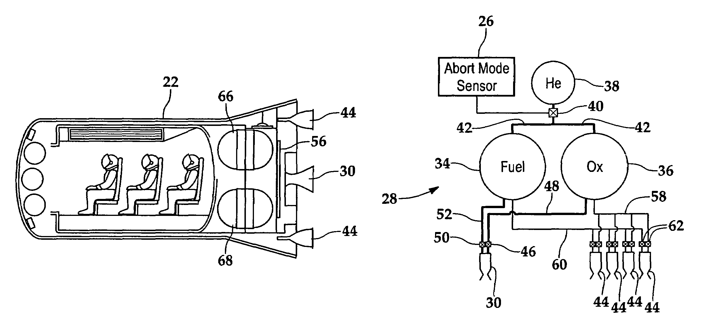
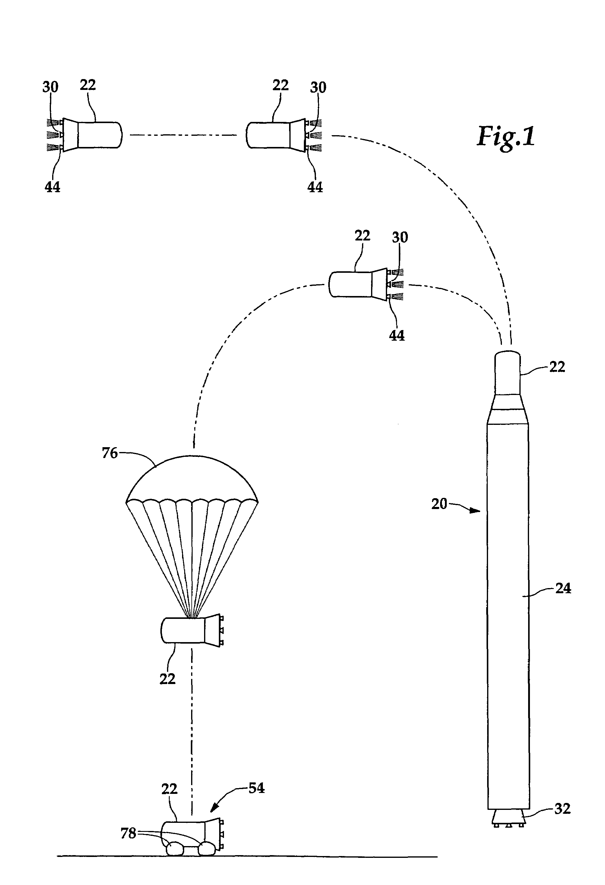
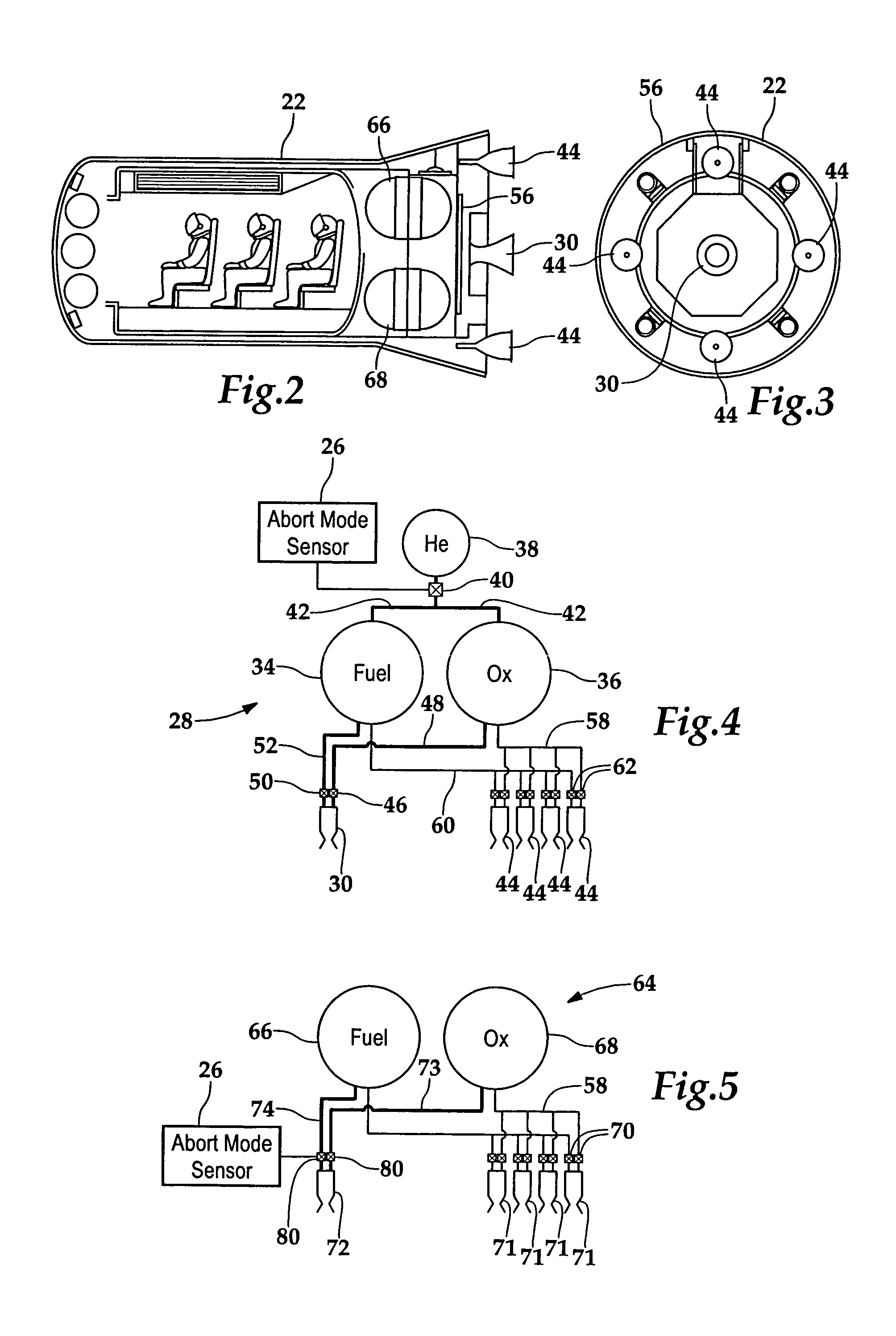
[0017]Referring more particularly to FIGS. 1-5, wherein like numbers refer to similar parts, an orbital stage system 20 is shown in FIG. 1. The orbital stage system 20 is comprised of an orbital stage 22 mounted to a lower stage 24. The orbital stage system 20 may launch from the ground, or be extracted from the cargo bay of an airplane, or be dropped from external storage on an airplane. If, during operation, the lower stage 24 for any reason fails to operate within a nominal range, an abort mode sensor 26, shown in FIG. 4, detects some failure or out-of-norm parameter, such as excessive yaw, pitch or roll rates, or some abnormal engine chamber pressure. Upon detection of a failure, the abort mode sensor 26 sends a signal to a propulsion system 28 which initiates firing of the abort engine 30. The abort engine 30 accelerate the orbital stage 22 away from the lower stage 24 at an acceleration of three, four, or more times the acceleration due to gravity at the Earth's surface. Such ...


PUM


Abstract

An orbital stage system has an orbital stage and one or more launch stages. The orbital stage incorporates an orbital maneuvering system (OMS) and an abort propulsion system which both utilize the same propellants, propellant tankage, and propellant pressurization system, but which employ radically different engines. The OMS engines are comprised of at least two engines which have a combined thrust in the neighborhood of 1 / 10 the weight of the orbital stage, an area ratio of 50 or more and an operating life of many hundred seconds, preferably many thousands of seconds or more. The abort engine may be a single engine and typically has a thrust of three, four, or more times the weight of the vehicle and an area ratio in the neighborhood of two and an operating life of at most a few tens of seconds.

Description

BACKGROUND OF THE INVENTION[0001]The present invention relates to orbital launch systems in general, and more particularly to manned orbital systems which incorporate a manned orbital stage.[0002]Launch vehicles, while continuing to improve in reliability, nevertheless have rates of failure which are a concern if they are used to transport people into space. As with high performance jet aircraft, which are also subject to rates of failure which would be considered high for military or commercial transport, the overall safety of a spacecraft which carries passengers is considerably enhanced if it is provided with a system for separating the passenger carrying portion of the vehicle from the other stage or stages of the launch vehicle. The Mercury and Apollo capsules, as well as Russian manned spacecraft have used a solid rocket motors which can pull the capsule away from the launch vehicle during the early portion of the boost phase. To reduce the performance penalty of carrying thes...

Claims


Application Information

Patent Timeline
Patent Type & Authority Patents(United States)
IPC IPC(8): B64G1/40B64G1/00
CPCB64G1/002B64G1/12B64G1/401B64G1/402F02K9/50B64G1/005
Inventor MCKINNEY, BEVIN C.HUDSON, GARY C.
Owner NEOSPACE INC
Why Eureka
Try Eureka