
Card edge connector

a card edge connector and connector technology, applied in the direction of fixed connections, coupling device connections, coupling parts engagement/disengagement, etc., can solve the problems of insecure connection of the card edge connector and inability to effectively enhance working efficiency, and achieve convenient assembling and disassembly, and simple structure.

Inactive Publication Date: 2009-02-03
LOTES
View PDF13 Cites 3 Cited by
  • Summary
  • Abstract
  • Description
  • Claims
  • Application Information

AI Technical Summary

Benefits of technology

[0009]Another object of the present invention is to provide a novel card edge connector, which has a simple structure and is convenient to assemble and disassemble so that the working efficiency can be effectively enhanced.
[0012]As compared to the prior art, the card edge connector of the present invention can be firmly connected onto a printed circuit board, has a simple structure, and is convenient to assemble and disassemble so that the working efficiency can be effectively enhanced.

Problems solved by technology

However, the fixation easily loosens, resulting in an insecure connection for the card edge connector.
Because the latch member of the above card edge connector has a complicated structure, occupies more space, and is inconvenient to assemble and disassemble, the working efficiency cannot be effectively enhanced.

Method used


Image

  • Card edge connector
  • Card edge connector
  • Card edge connector

Examples


Embodiment Construction

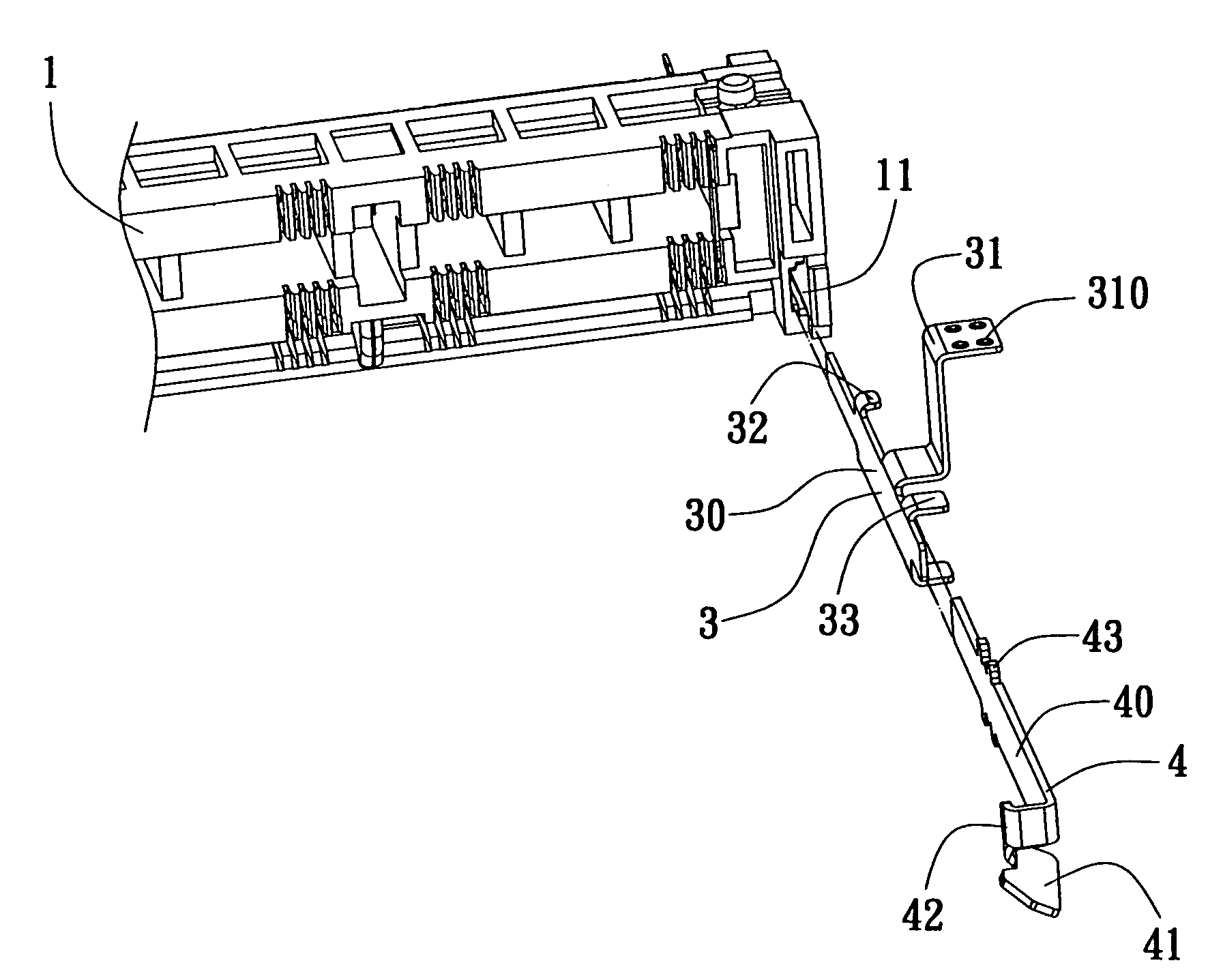
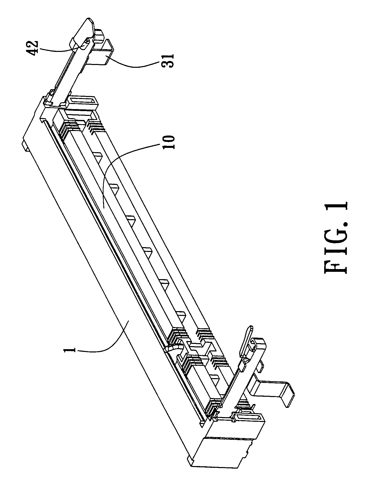
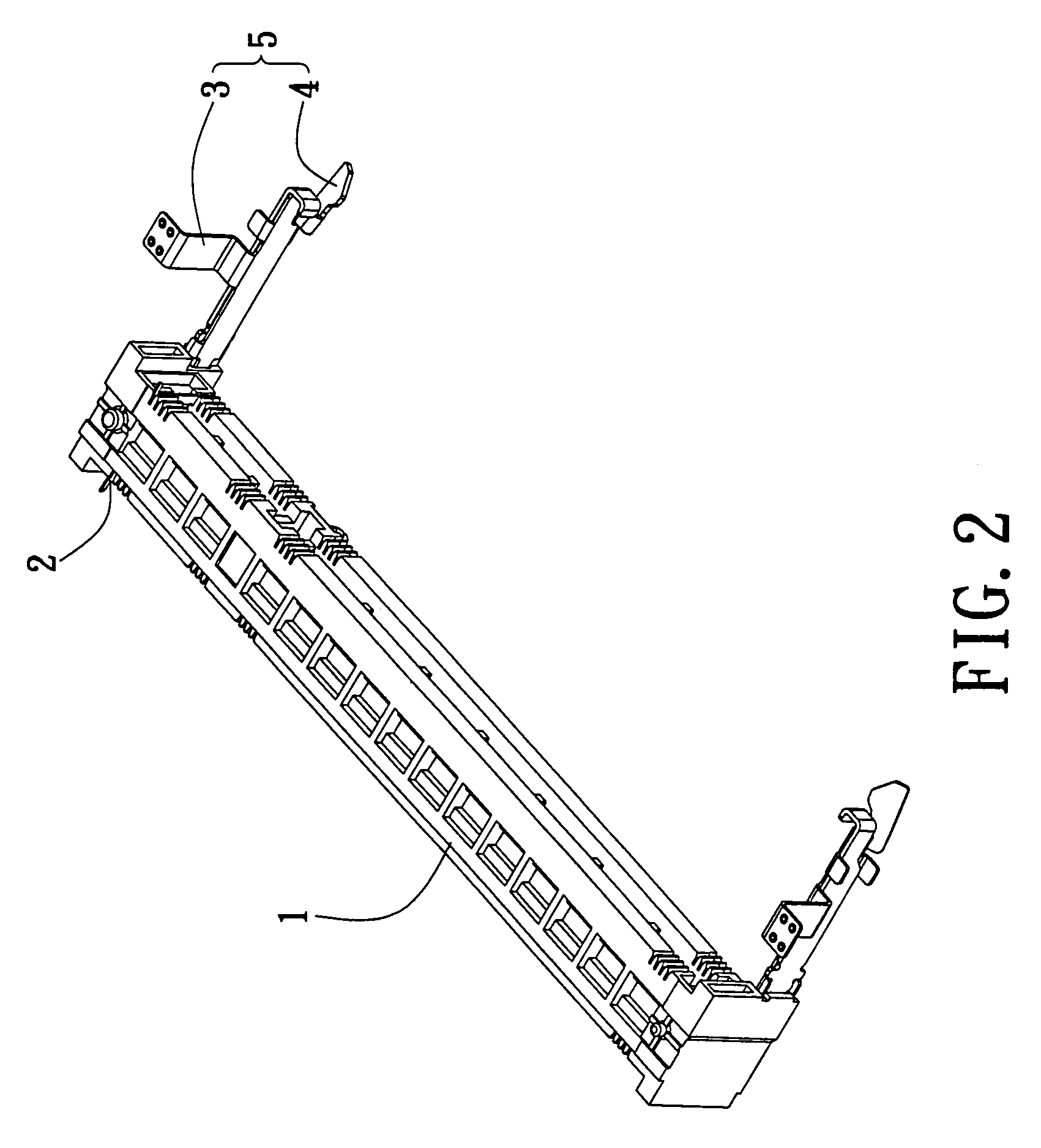
[0019]As shown in FIGS. 1 to 3, a card edge connector of the present invention can be used to bear a mating electronic component (not shown). The card edge connector comprises an insulator body 1 and a pair of metal components 3. The insulator body has a longitudinal shape, and has a central slot 10 provided along its longitudinal direction. Conducting terminals 2 are disposed on both sides of the central slot 10, and are mechanically and electrically connected with a memory module (not shown). A stepped groove 11 is disposed at the distal end of both of the opposite sides of the insulator body 1. The pair of metal components 3 is disposed in the grooves 11 at the distal ends of the two opposite sides of the insulator body 1. Each of the metal components 3 includes a main body member 30 fixed on the insulator body 1 and a fixing member 31 capable of being soldered to a printed circuit board. At least a soldering point 310 is protrudingly disposed on the fixing member 31. In this emb...


PUM


Abstract

A card edge connector comprises an insulator body and a pair of metal components. A central slot is provided along the longitudinal direction of the insulator body. The pair of metal components is disposed at distal ends of two opposite sides of the insulator body. Each metal component includes a main body member fixed on the insulator body and a fixing member soldered to a printed circuit board. At least one soldering point is protrudingly provided on the fixing member. The proposed card edge connector can effectively save space, and has a simple structure. Moreover, it can be conveniently manufactured to enhance production efficiency, can be easily installed or dismantled, and can be firmly connected to a printed circuit board.

Description

BACKGROUND OF THE INVENTION[0001]1. Field of the Invention[0002]The present invention relates to a card edge connector and, more particularly, to a card edge connector capable of firmly connecting with a printed circuit board.[0003]2. Description of Related Art[0004]A prior art card edge connector is commonly used in the industry to connect a memory module to a printed circuit board and comprises a longitudinal insulator body and a pair of metal components. The insulator body has a central slot to bear the memory module. Some conducting terminals are disposed on both sides of the central slot, and are mechanically and electrically connected with the memory module. The pair of metal components is disposed at distal ends of two opposite sides of the insulator body. Each metal component includes a main body member fixed on the insulator body and a fixing member for soldering to a printed circuit board. The prior art card edge connector is fixed onto the printed circuit board through th...

Claims


Application Information

Patent Timeline
Patent Type & Authority Patents(United States)
IPC IPC(8): H01R4/10
CPCH01R23/72H01R12/7052H01R12/707H01R12/721H01R12/52
Inventor JU, TED
Owner LOTES
Learn More