Cable connector retention device
- Summary
- Abstract
- Description
- Claims
- Application Information
AI Technical Summary
Benefits of technology
Problems solved by technology
Method used
Image

Examples
embodiment 100
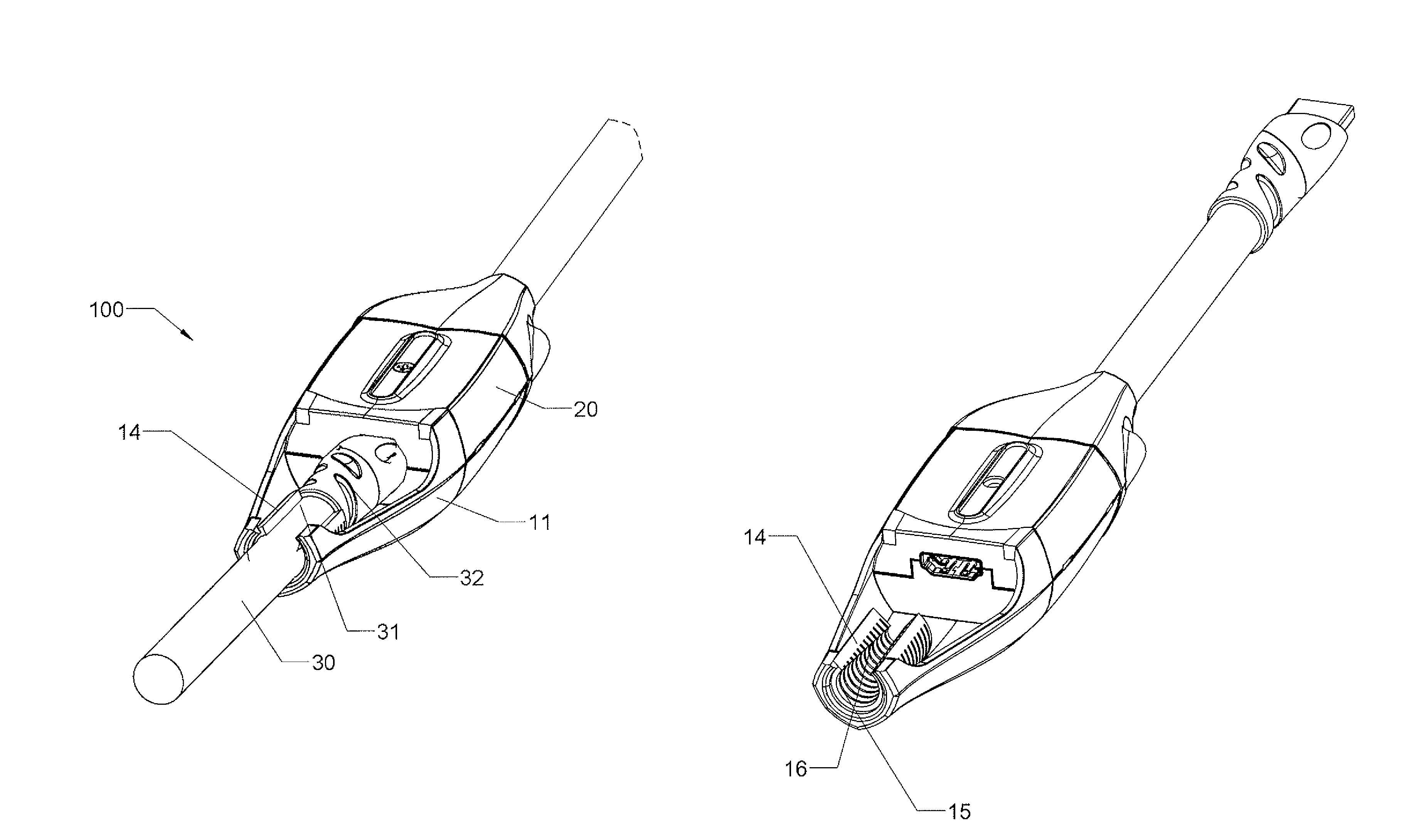
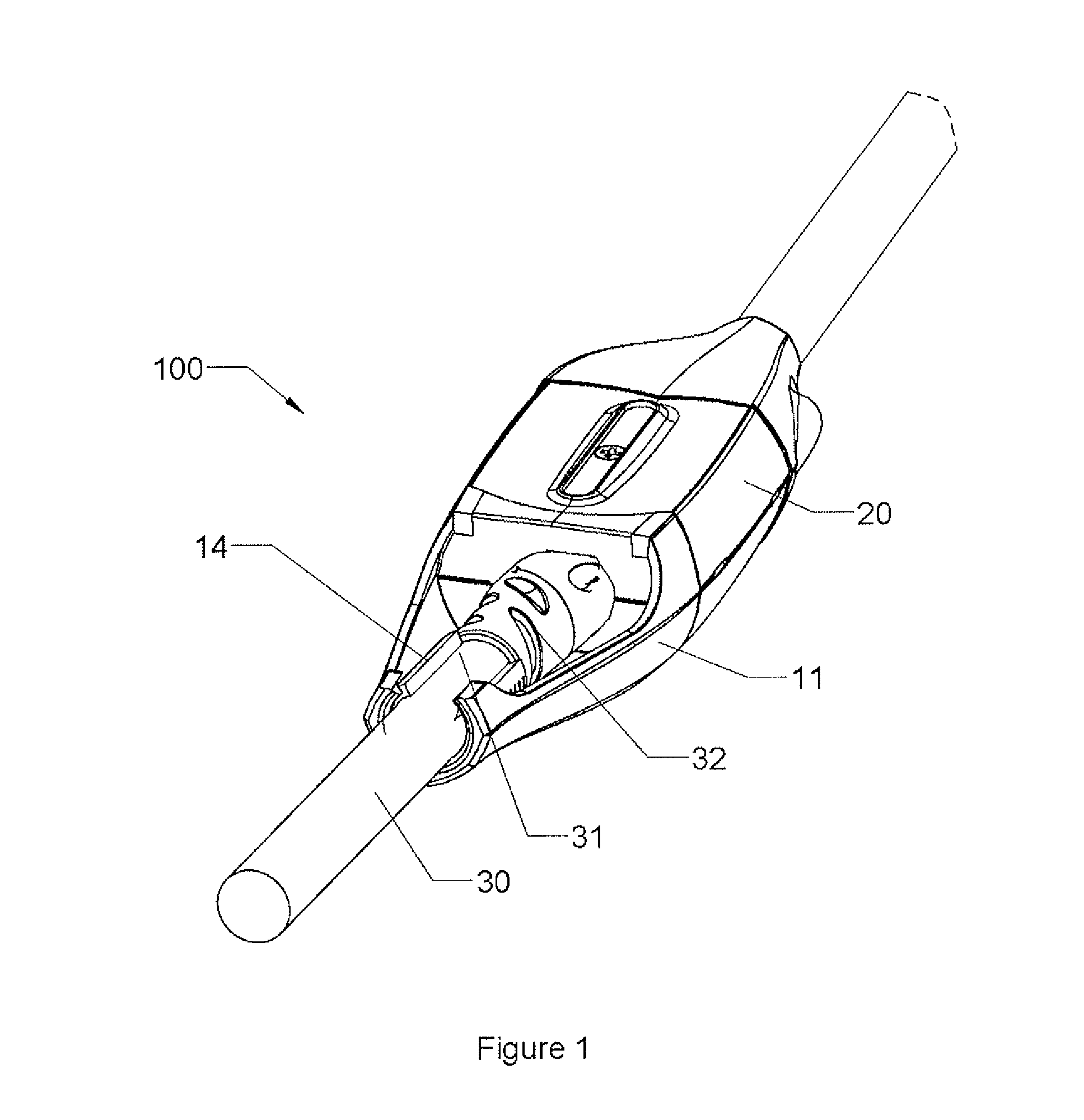
[0012]FIG. 1 illustrates, in a perspective view, an embodiment 100 of the present invention, comprising a segment 11 coupled at one end to connector 20. Segment 11 extends lengthwise along a cable 30 that is connected to connector 20. A second end of segment 11 is coupled to a tubular grip 14. Grip 14 secures the cable in place by grasping the cable along a length 31 at or near its strain-relief boot 32.
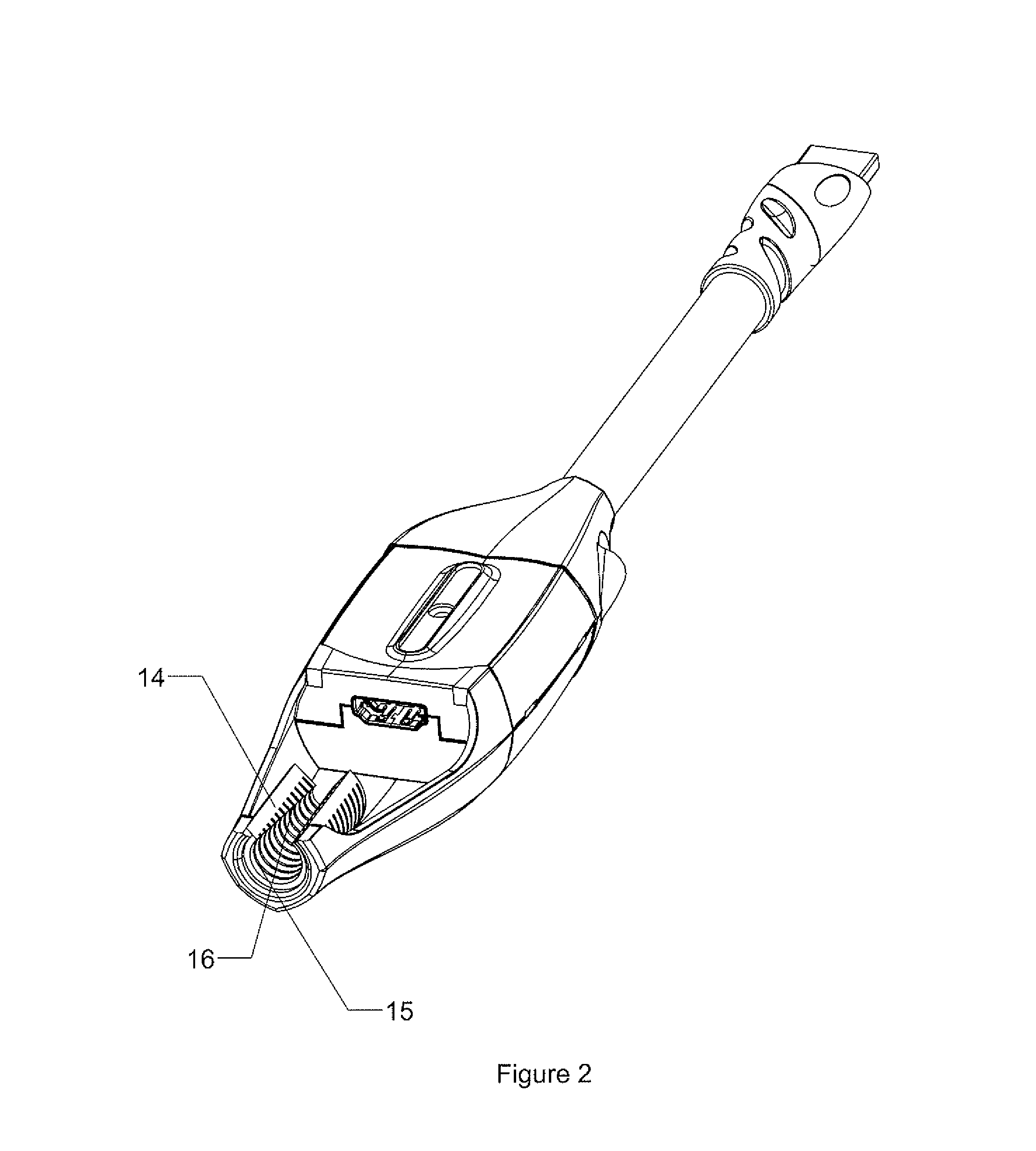
[0013]As shown in FIG. 2, in an embodiment of the present invention, grip 14 comprises a tube with a portion of its periphery cut away, resulting in a C-shaped cross section. A series of parallel or spiraled grooves 15 are formed along the internal surface 16 of grip 14, which is tapered or conically contoured to provide increasing interference fit along its length with the surface of cable 31 at or near its strain-relief boot 32. The grip 14 may be composed of any material that is flexible enough to accommodate insertion of a cable, yet rigid enough to provide adequate support and p...
second embodiment
[0019]FIG. 3 illustrates, in a perspective view, the present invention which comprises coupler 200 having two of the presently described cable retention devices which are coupled to an adapter at opposing ends. This embodiment provides support and protection for two cables that are linked by the adapter. As such a linkage is often employed to extend cables, this embodiment represents a particularly useful application of the invention because extended cables run for long distances and are thus especially susceptible to events that may dislodge their connections.
[0020]No special materials are required to construct the retention device of the present invention. Typically, the device can be molded in one or several pieces, depending on desired configuration, using the same materials used in the construction of cable connector shells and boots. In particular, it may be desirable to form tubular grip 14 separately for fixed attachment to segment 11 during assembly.
PUM
 Abstract
Description
Claims
Application Information
 - Generate Ideas
- Intellectual Property
- Life Sciences
- Materials
- Tech Scout
- Unparalleled Data Quality
- Higher Quality Content
- 60% Fewer Hallucinations
Browse by: Latest US Patents, China's latest patents, Technical Efficacy Thesaurus, Application Domain, Technology Topic, Popular Technical Reports.
© 2025 PatSnap. All rights reserved.Legal|Privacy policy|Modern Slavery Act Transparency Statement|Sitemap|About US| Contact US: help@patsnap.com