Electrical switching apparatus and adjustable mounting assembly therefor

a technology of electrical switching apparatus and mounting assembly, which is applied in the direction of switchgear with a retractable carriage, non-enclosed substations, substations, etc., can solve the problems of power circuit breakers that vibrate within, separate or break, and damage severe electrical equipmen

Active Publication Date: 2009-02-03
EATON INTELLIGENT POWER LTD
View PDF3 Cites 15 Cited by
  • Summary
  • Abstract
  • Description
  • Claims
  • Application Information

AI Technical Summary

Benefits of technology

[0011]The bracket may include as the guide portion, a first guide portion and a second guide portion. The moveable block may include first and second moveable blocks disposed within the first and second guide portions, respectively, and each of the first and second moveable blocks may include one jack screw and a first slot and a second slot each having one lock screw disposed therein. The locking mechanism may further include at least one locknut disposed on the jack screw wherein the locknut is structured to be tightened on the jack screw in order to further secure the position of the moveable block. The bracket may be made from a metallic material wherein the engagement portion of the bracket includes a resilient protector structured to further resist the aforementioned damage potentially caused by the impact force. The bracket may be coupled to the first and second sidewalls by a plurality of fasteners wherein the fasteners are structured to be tightened and loosed in order to adjust the bracket thereby further facilitating adjustment and securement between the frame and the housing of the electrical switching apparatus.

Problems solved by technology

All shock loads can severely damage the electrical equipment.
Additionally, it is generally well known that power circuit breakers are typically large in size and relatively heavy and are, therefore, often mounted with other switchgear in a cabinet or other enclosure.
In addition to the aforementioned undesired cracking of the molded housing of the circuit breaker, large shock loads could further cause the power circuit breaker to vibrate within, or separate or break-away from the cassette.

Method used


Image

  • Electrical switching apparatus and adjustable mounting assembly therefor
  • Electrical switching apparatus and adjustable mounting assembly therefor
  • Electrical switching apparatus and adjustable mounting assembly therefor

Examples


Embodiment Construction

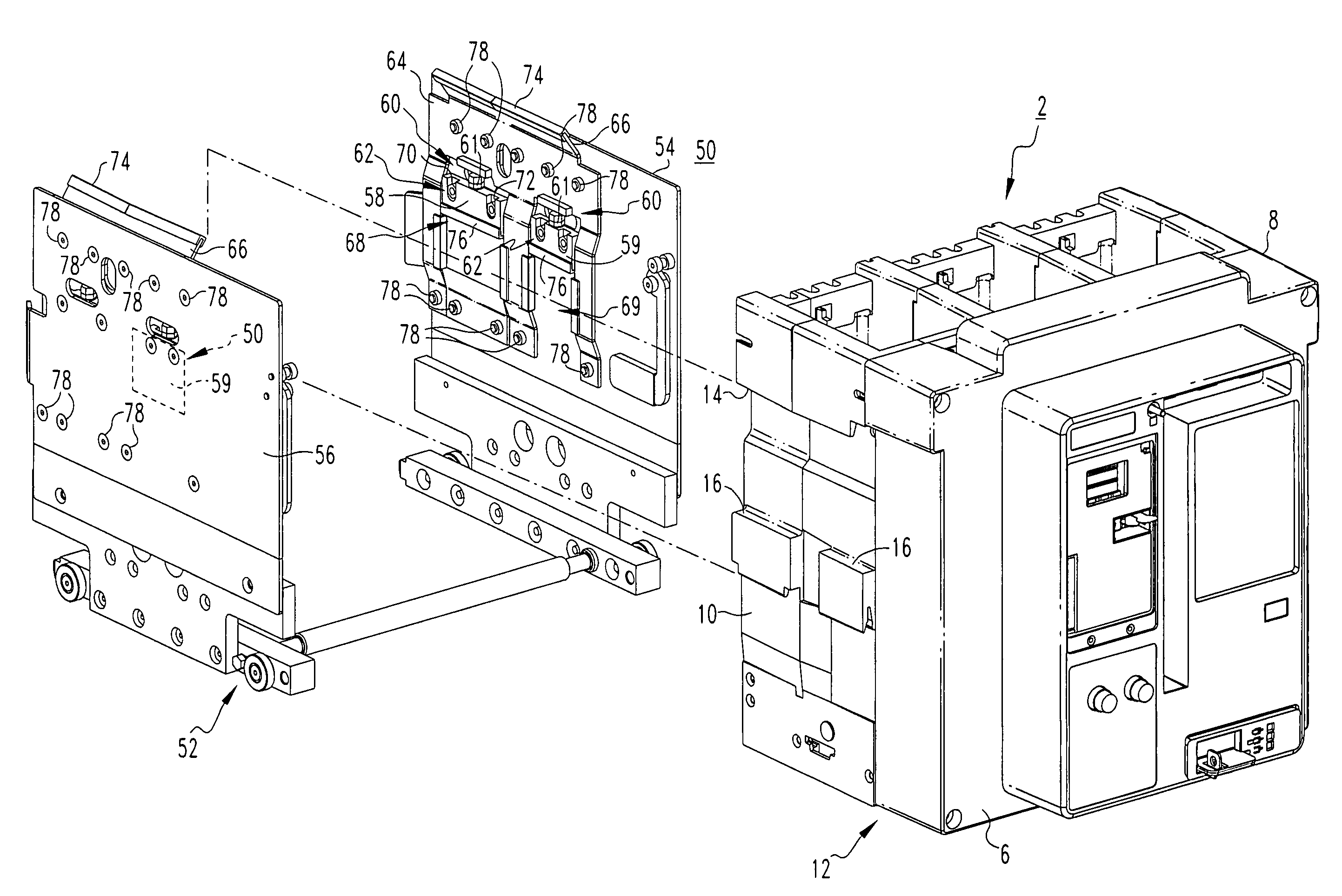
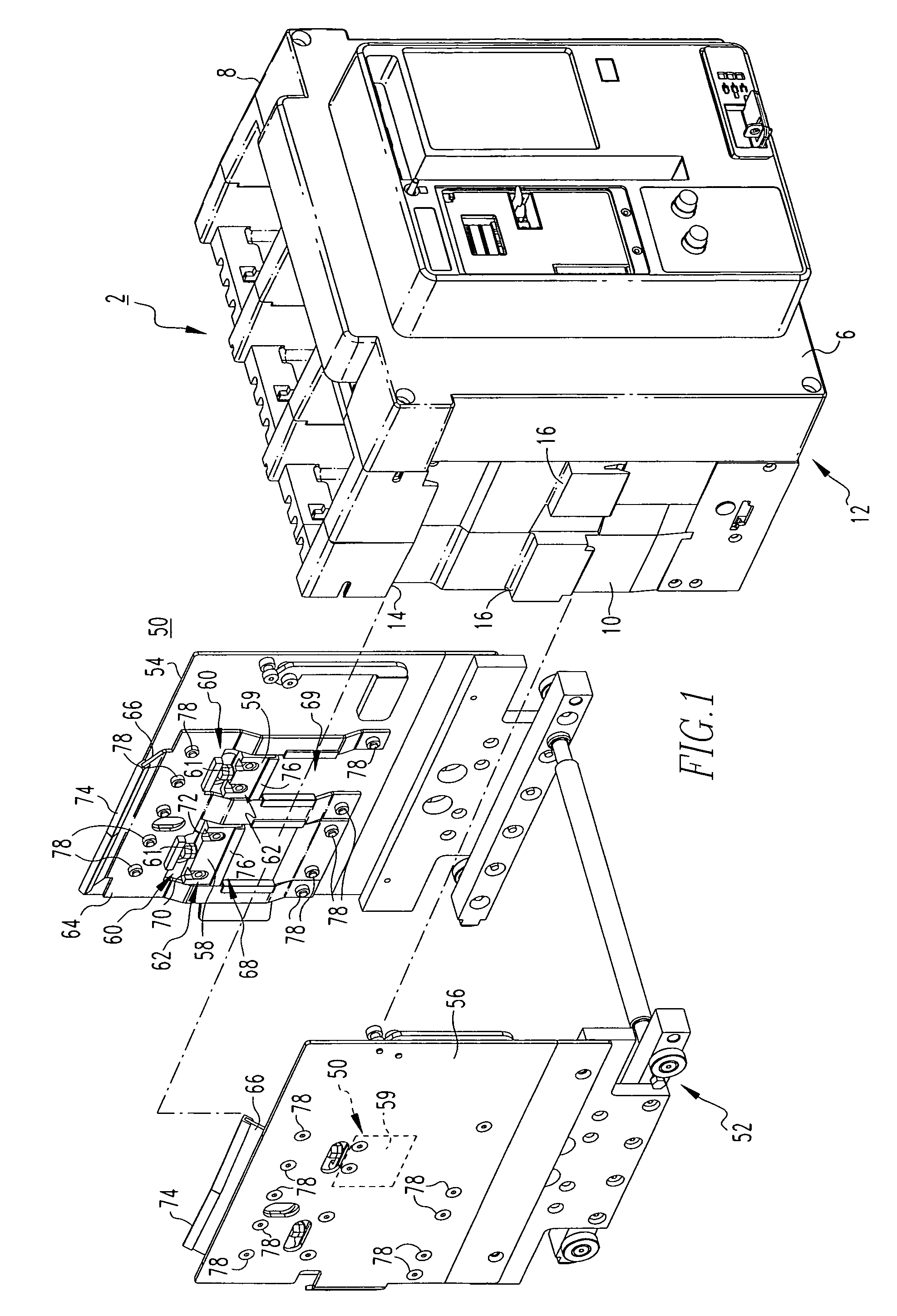
[0021]For purposes of illustration, the invention will be described as applied to electrical apparatus employed in naval applications (e.g., without limitation, water-based vehicles, such as ships, boats, aircraft carriers, other vessels for travel on water, and submarines, or other vehicles for travel under water), although it will become apparent that it could also be applied to other applications such as, for example, in a land vehicle, air vehicle, or other suitable structure.

[0022]Directional phrases used herein, such as, for example, up, down, top, bottom, left, right and derivatives thereof, relate to the orientation of the elements shown in the drawings and are not limiting upon the claims unless expressly recited therein.

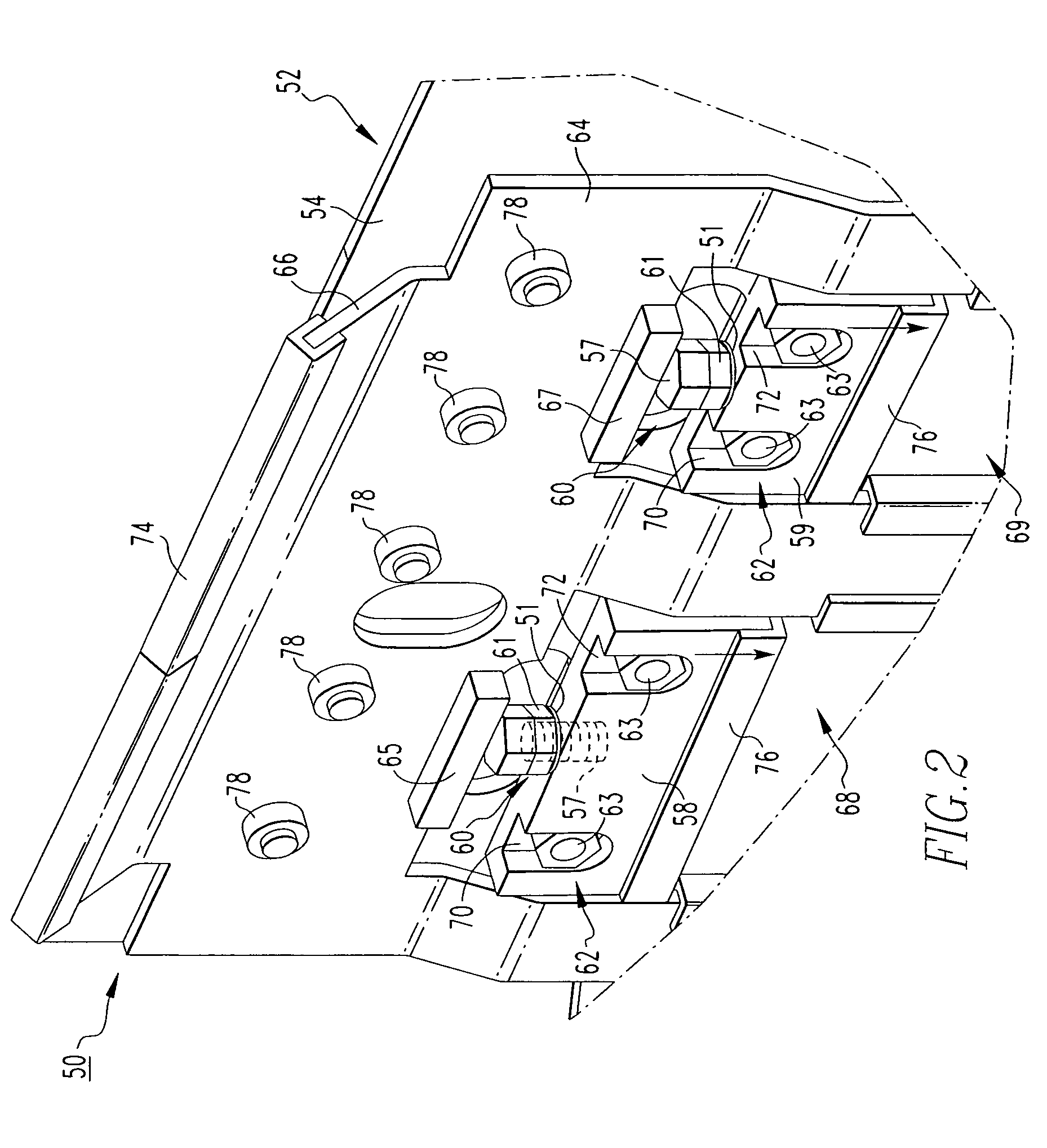
[0023]As employed herein, the term “fastener” refers to any suitable connecting or tightening mechanism expressly including, but not limited to, screws, bolts and the combinations of bolts and nuts (e.g., without limitation, lock nuts) and bolts, washers (e...


PUM


Abstract

An adjustable mounting assembly for a power circuit breaker includes a frame having a first sidewall disposed opposite a first side of the housing of the power circuit breaker and a second sidewall disposed opposite the second side of the housing. At least one moveable block is disposed between the first and second sidewalls of the frame and the corresponding first and second sides of the housing. An adjustment mechanism, such as a jackscrew coupled to the moveable block, adjusts in order to move the block into engagement with the corresponding sides of the housing. A fastening mechanism, such as a lock screw, secures the moveable block and the frame with respect to the housing. The adjustable mounting assembly securely mounts the frame and the power circuit breaker within a switchgear enclosure in order to resist damage potentially caused by an impact force sustained thereby.

Description

BACKGROUND OF THE INVENTION[0001]1. Field of the Invention[0002]The present invention relates generally to electrical switching apparatus and, more particularly, to a circuit breaker including an adjustable mounting assembly. The invention also relates to an adjustable mounting assembly for circuit breakers.[0003]2. Background Information[0004]In certain applications, such as, for example and without limitation, naval applications (e.g., without limitation, water-based vehicles, such as ships, boats, aircraft carriers, other vessels for travel on water, and submarines, or other vehicles for travel under water), electrical equipment must be designed to withstand large shock loads (e.g., up to about 1000 times the force of gravity, or more). Such shock loads include, for example, impact loads resulting from a direct hit by a torpedo, depth charge, missile, other ammunition or impact force, as well as residual or aftershock loads caused, for example, by a nearby indirect explosion, suc...

Claims


Application Information

Patent Timeline
Patent Type & Authority Patents(United States)
IPC IPC(8): H01H9/00H01H11/00
CPCH01H71/02H01H3/60H02B1/54
Inventor GOTTSCHALK, ANDREW L.
Owner EATON INTELLIGENT POWER LTD
Why Eureka
Try Eureka