
Magnetic data system having bias circuit with bias resistor

a bias resistor and data system technology, applied in the field of magnetic data system with bias resistor, can solve the problems of strong involvement of voltages, magnetic heads tend to suffer from adverse tribological interactions, and adverse tribological effects, and achieve the effect of reducing wear, corrosion and accumulation

Inactive Publication Date: 2009-02-03
INT BUSINESS MASCH CORP
View PDF10 Cites 45 Cited by
  • Summary
  • Abstract
  • Description
  • Claims
  • Application Information

AI Technical Summary

Benefits of technology

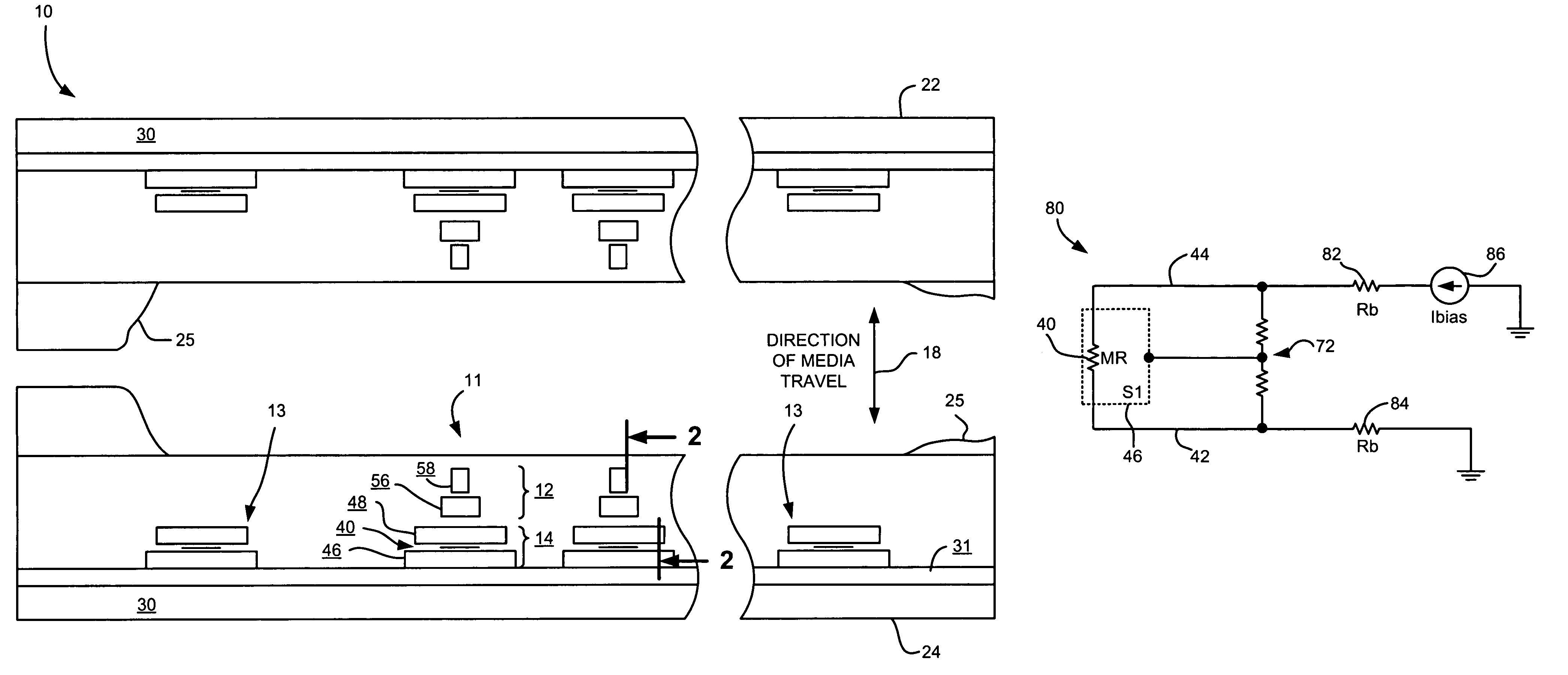
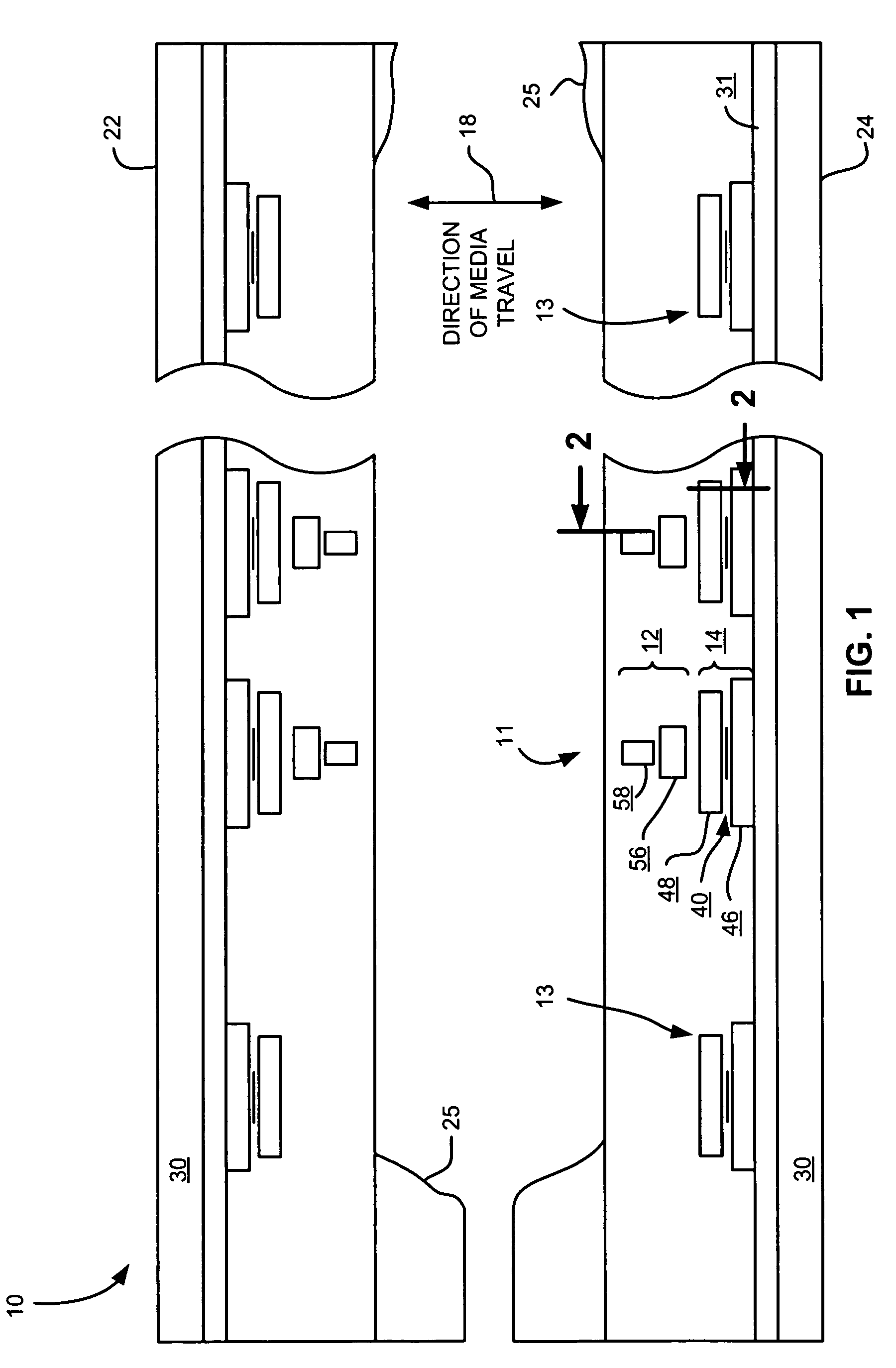
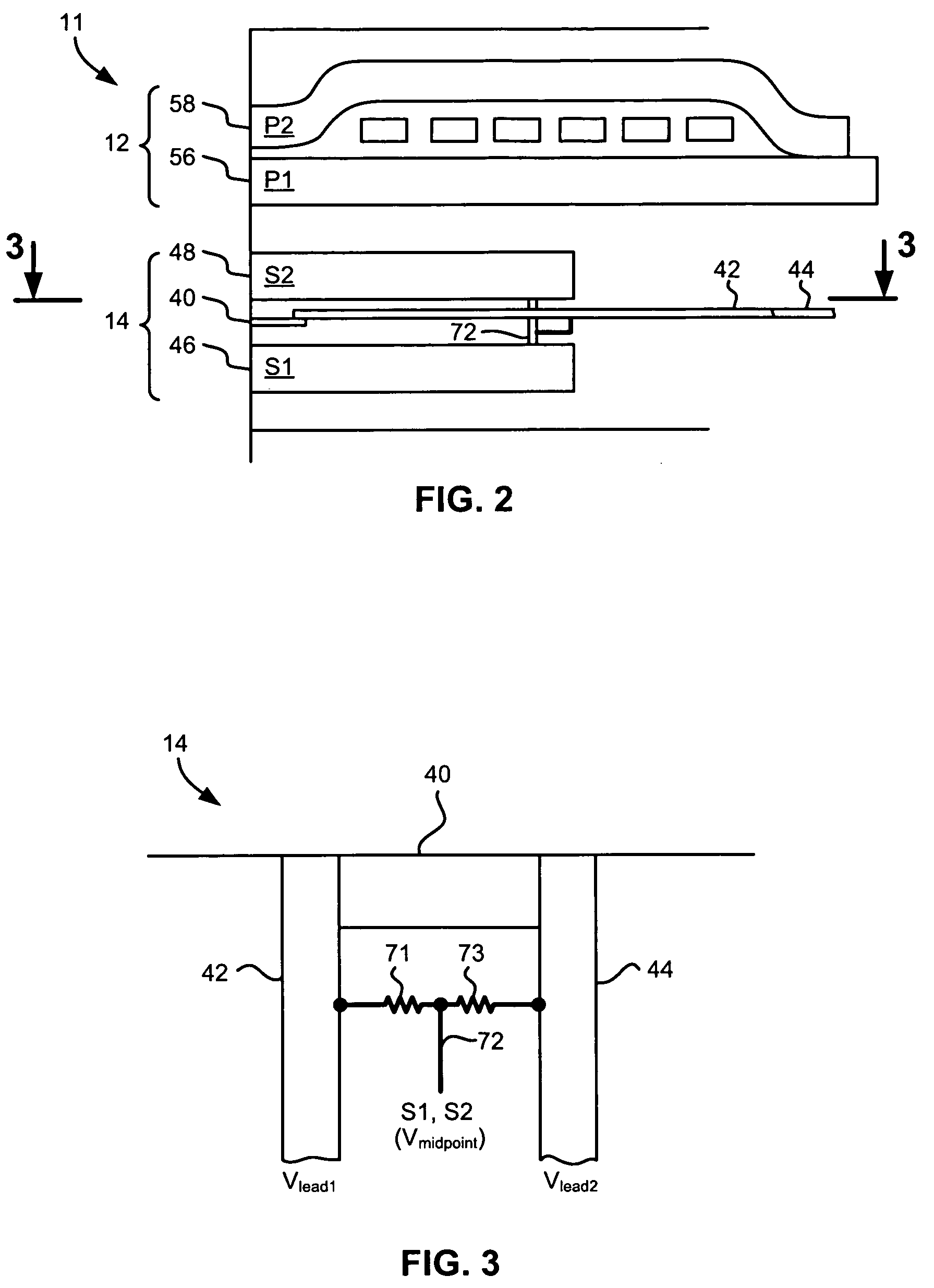
[0014]A magnetic data system according to one embodiment includes at least one reader formed above a substrate, the at least one reader further comprising a shield and a magnetoresistive (MR) sensor. A first circuit sets a voltage (Vsub) of the substrate to about a voltage (Vshield) of the shield of the at least one reader. Because the substrate and shield are at similar voltage levels, tribological effects such as wear, corrosion and accumulations are reduced. Further, the probability of an electrical discharge, e.g., spark, occurring between the shield and the sensor is minimized.

Problems solved by technology

These high fields are associated with adverse tribological effects, including electrostatic debris deposition and pitting of the head insulator due to electric discharges.
Due to the varying voltage differentials and irregular electric fields between the various parts of a head as well as between head and tape, magnetic heads tend to suffer from adverse tribological interactions, which include electrical discharge, tape changes, head erosion, debris buildup, chemical conversion, head sensor shorting, etc.
Such voltages are strongly implicated in unfavorable tribological processes such as electrochemical reactions, electrostatic accumulation of debris, and even certain types of wear.
The voltage differences between the adjacent reader shield and substrate is problematic due to their close proximity, and is compounded by the potentially large localized electric fields created by a conductive substrate, e.g., of AlTiC.
Several solutions have been contemplated, but each of these have drawbacks.
However, if the reader shields are not clamped to ground, the voltage differential leads to the aforementioned tribological effects between the shields and substrate.
Grounding the shields in a multi-sensor head is generally impractical.
Even if the shields are grounded, adverse tribological effects may occur depending on the tape electrical and mechanical characteristics and other aspects of the tape path, such as ground or floating of guides.
Another problem encountered is that the readers are susceptible to shield-shorting which may occur in combination with substrate shorting, as a result of running magnetic recording tape having insufficient lubricity across the head at very low humidity, which in turn is found to produce accumulations of conductive material on the MR element, shields and substrate.
Shorting is a well-known cause of reading errors.
For instance, forcibly recessing the sensor so that its components do not develop the conductive accumulation is difficult to manufacture, and also generally produces undesirable spacing loss for the data readers, which must read much higher frequencies than the servo readers.

Method used


Image

  • Magnetic data system having bias circuit with bias resistor
  • Magnetic data system having bias circuit with bias resistor
  • Magnetic data system having bias circuit with bias resistor

Examples


Embodiment Construction

[0031]The following description is the best mode presently contemplated for carrying out the present invention. This description is made for the purpose of illustrating the general principles of the present invention and is not meant to limit the inventive concepts claimed herein. Further, particular features described herein can be used in combination with other described features in each of the various possible combinations and permutations.

[0032]In the drawings, like and equivalent elements are numbered the same throughout the various figures.

[0033]The present invention reduces susceptibility to shorting and improves tribological characteristics in MR devices such as magnetic heads by matching as closely as possible the substrate and shield voltages. Accordingly, should debris accumulate and create a short from the sensor to the substrate, the low or nonexistent voltage differential therebetween greatly mitigates the effects of such a short.

[0034]It should be noted that while muc...


PUM

PropertyMeasurementUnit
electric fieldaaaaaaaaaa
voltageaaaaaaaaaa
impedanceaaaaaaaaaa

Abstract

A magnetic data system according to one embodiment includes at least one reader formed above a substrate, the at least one reader further comprising a shield and a magnetoresistive (MR) sensor. A first circuit sets a voltage (Vsub) of the substrate to about a voltage (Vshield) of the shield of the at least one reader.

Description

FIELD OF THE INVENTION[0001]The present invention relates to magnetoresistive (MR) devices, and more particularly, this invention relates to an MR device having an electrically biased substrate.BACKGROUND OF THE INVENTION[0002]Business, science and entertainment applications depend upon computers to process and record data, often with large volumes of the data being stored or transferred to nonvolatile storage media, such as magnetic discs, magnetic tape cartridges, optical disk cartridges, floppy diskettes, or floptical diskettes. Typically, magnetic tape is the most economical means of storing or archiving the data. Storage technology is continually pushed to increase storage capacity and storage reliability. Improvement in data storage densities in magnetic storage media, for example, has resulted from improved medium materials, improved error correction techniques and decreased areal bit sizes. The data capacity of half-inch magnetic tape, for example, is now measured in hundred...

Claims


Application Information

Patent Timeline
Patent Type & Authority Patents(United States)
IPC IPC(8): G11B5/265G11B5/29
CPCG11B5/3912G11B2005/0016
Inventor BISKEBORN, ROBERT GLENN
Owner INT BUSINESS MASCH CORP
Learn More