DDR interface for reducing SSO/SSI noise

a ddr interface and noise reduction technology, applied in the field of ddr interface for reducing sso/ssi noise, can solve the problems of duty cycle distortion, affecting ddr operation directly, and skews within the data bus, so as to improve ddr bandwidth, enhance ddr interface, and reduce sso and ssi noise in ddr interface.

Inactive Publication Date: 2009-02-03
CISCO TECH INC
View PDF12 Cites 29 Cited by
  • Summary
  • Abstract
  • Description
  • Claims
  • Application Information

AI Technical Summary

Benefits of technology

The invention introduces an improvedDDR interface that reduces interference between signals (known as SSO or SSI), resulting in better performance and higher efficiency for memory devices. This enhancement increases the speed at which data moves through the device while reducing the amount of power needed. It also simplifies the overall design process by requiring fewer components. Overall, this innovation leads to faster, more reliable memories with greater capacity.

Problems solved by technology

The technical problem addressed in this patent is how to reduce the negative effects of double data rate (DDR)-related issues such as clock jitter, clock duty cycle distortion, and skews within the data bus while maintaining high operational frequencies without adding more pins or requiring expensive solutions like differential signaling and dynamic clock alignment circuits.

Method used


Image

  • DDR interface for reducing SSO/SSI noise
  • DDR interface for reducing SSO/SSI noise
  • DDR interface for reducing SSO/SSI noise

Examples


Embodiment Construction

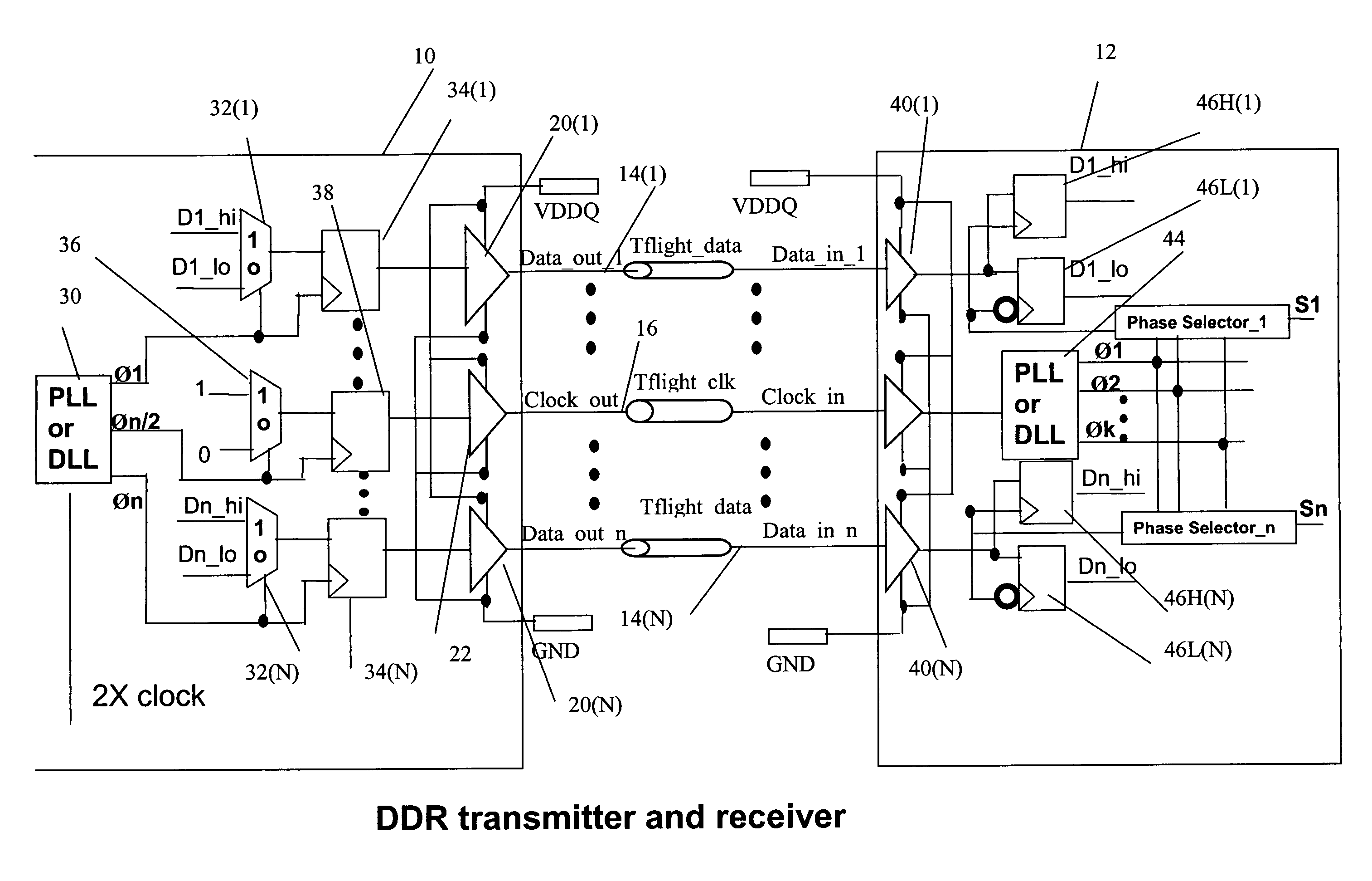
[0020]Reference will now be made in detail to various embodiments of the invention. Examples of these embodiments are illustrated in the accompanying drawings. While the invention will be described in conjunction with these embodiments, it will be understood that it is not intended to limit the invention to any embodiment. On the contrary, it is intended to cover alternatives, modifications, and equivalents as may be included within the spirit and scope of the invention as defined by the appended claims. In the following description, numerous specific details are set forth in order to provide a thorough understanding of the various embodiments. However, the present invention may be practiced without some or all of these specific details. In other instances, well known process operations have not been described in detail in order not to unnecessarily obscure the present invention. FIG. 3 depicts an embodiment of the invention.

[0021]FIG. 3 depicts a Transmitter (Tx) 10 and Receiver (R...


PUM


Abstract

An improved DDR interface uses single-ended technology and phase-shifts all output data signals and the output source clock signal so that each output signal switches at a different time so that IDDQ spikes caused by I/O switching do not accumulate. A dynamic phase adjustment circuit on the receiver compensates for the phase differences. Clock jitter and skew is reduced and the number of IDDQ pins is reduced to provide a more effective design and high density package.

Description


Claims


Application Information

Patent Timeline
Owner CISCO TECH INC
Why Eureka
Try Eureka