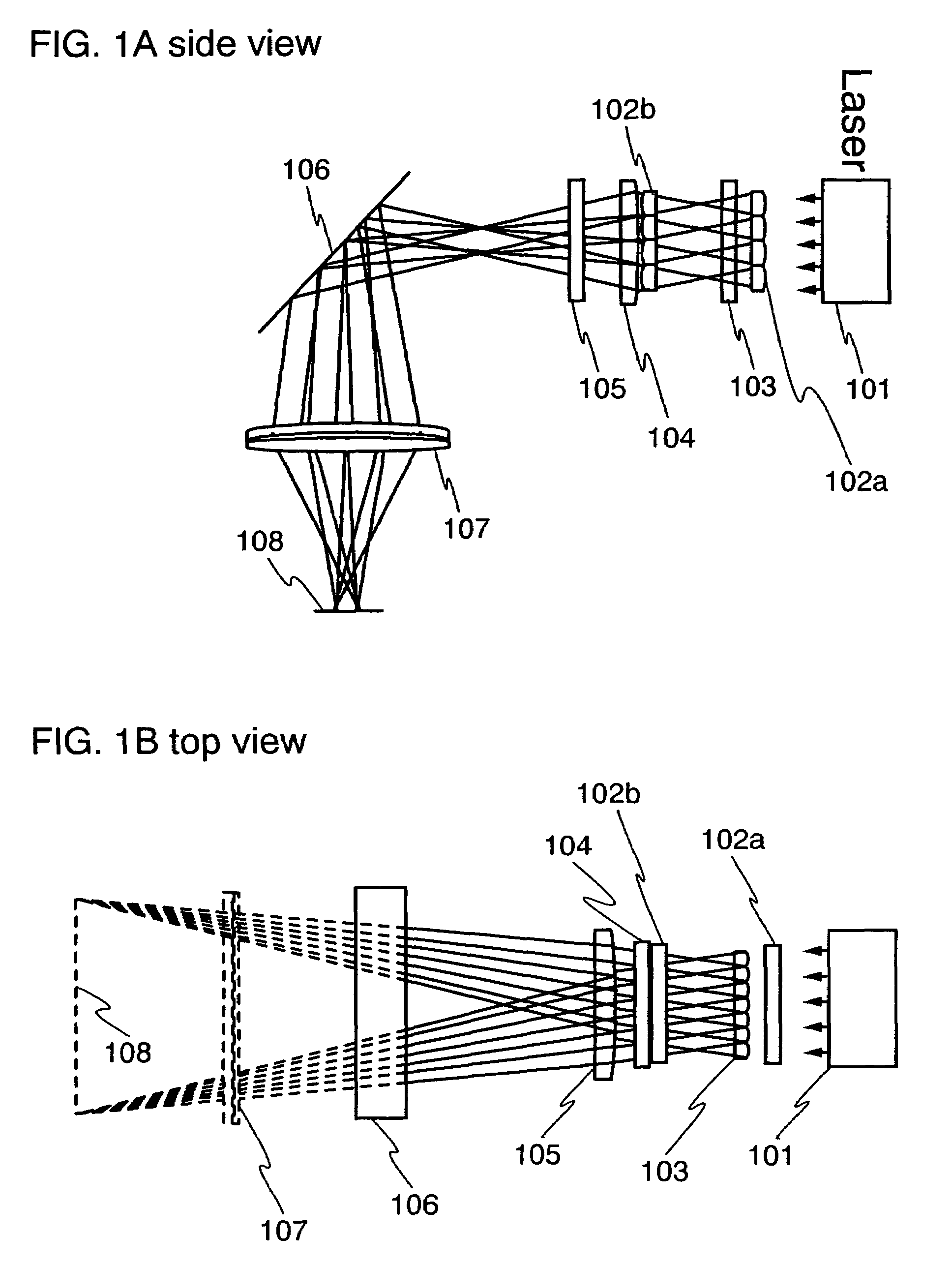
Beam homogenizer and laser irradiation apparatus
a laser irradiation and beam homogenizer technology, applied in the direction of lenses, manufacturing tools, instruments, etc., can solve the problem of difficult design of optical systems to form desired laser beams, and achieve the effect of increasing the degree of freedom in designing optical systems and extending the range of motion
- Summary
- Abstract
- Description
- Claims
- Application Information
AI Technical Summary
Benefits of technology
Problems solved by technology
Method used
Image
Examples
embodiment mode 1
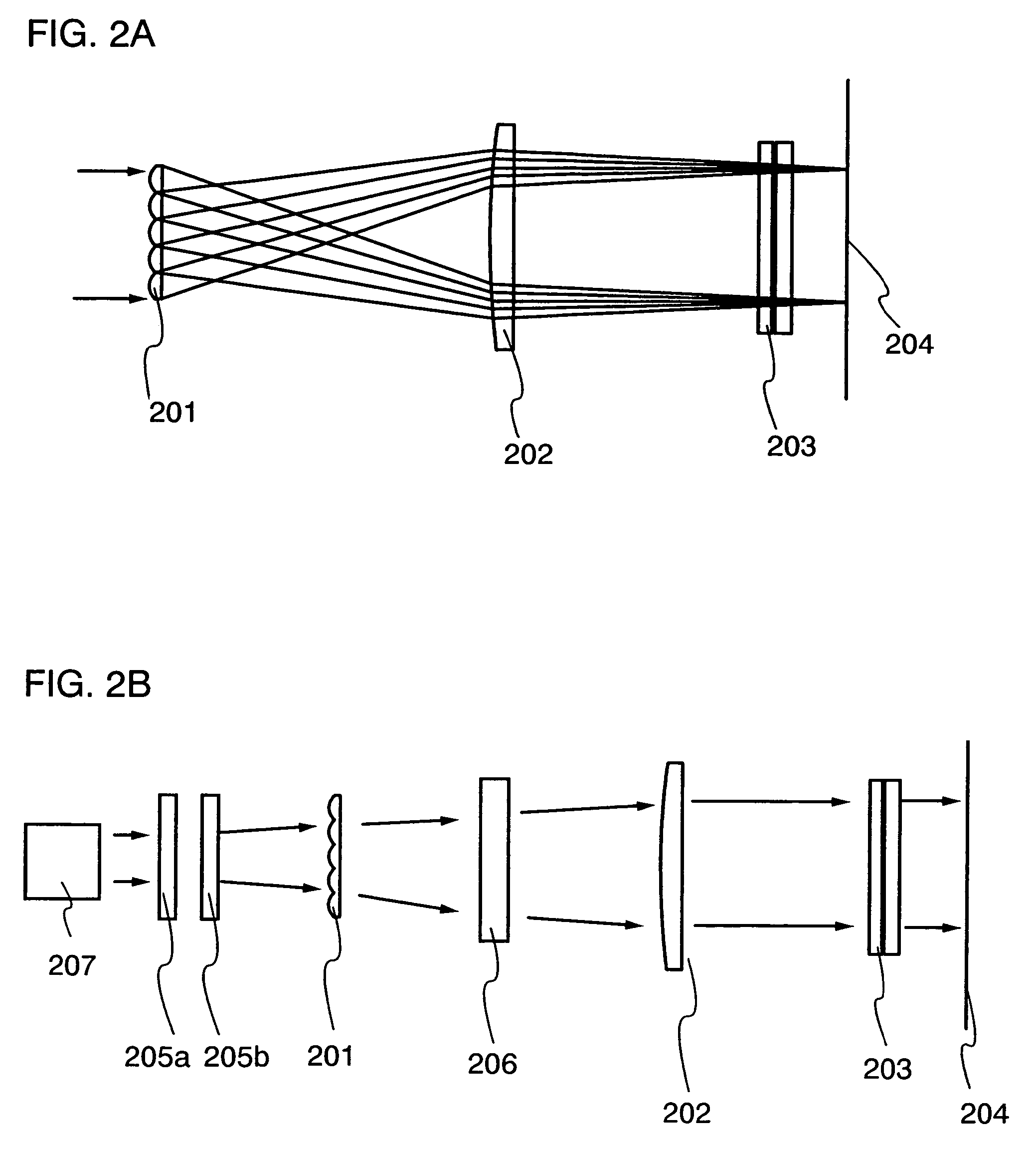
[0044]In the present embodiment mode, a long-side of a linear beam is formed by using an off-axis cylindrical lens array and a converging lens for a long-side direction. The advantage of this optical system is that the distance from the converging lens for the long-side direction to an irradiation surface can be designed freely as described below.
[0045]Parameters of the off-axis cylindrical lens array and the converging lens constituting the optical system are described with reference to FIGS. 6A to 6C.
[0046]FIG. 6A is a drawing for describing an optical system of the present embodiment mode. In this figure, a laser beam is divided by an off-axis cylindrical lens array 601, the divided laser beams are converged by a lens 602 in a long-side direction, and the divided laser beams are superposed in the same region on an irradiation surface 603.
[0047]In this specification, n is the refractive index of the lens, i is an identification number of the lens in the off-axis cylindrical lens a...
embodiment mode 2
[0059]In the optical system of this embodiment mode, the irradiation surface (an imaging point) is conjugated with the hypothetical object point formed between the off-axis cylindrical lens array and the light source. Here, an example is described in which a parallel beam is incident into an off-axis cylindrical lens constituting an off-axis cylindrical lens array 1201 with reference to FIG. 12. It is noted that the parallel beam incident into the off-axis cylindrical lens is illustrated as a beam 1202. An intersection of a center axis 1208 of the off-axis cylindrical lens with a first surface of the off-axis cylindrical lens is illustrated as an intersection 1209. Here, a ray connecting the intersection 1209 with a focal point 1210 of the parallel beam formed between the off-axis cylindrical lens array 1201 and a converging lens 1205 for a long-side direction is extended to the side of the light source. When the rays from any two off-axis cylindrical lenses constituting the off-axi...
embodiment 1
[0061]It is considered that the stripes appearing in parallel with the scanning direction of the laser beam mainly result from striae of the lens constituting the optical system or dust that is attached to the surface of the lens and burned by the laser irradiation. The inhomogeneous transmittance of the lens due to such an inhomogeneous region may cause the stripes. Moreover, when the rays divided to form the beam that is homogeneous in the long-side direction transmit through the region having the inhomogeneous transmittance, stripes may appear at regular intervals.
[0062]In order to suppress such stripes, the cylindrical lens array acting on the long-side direction of the linear beam is preferably set closer to the irradiation surface. In particular, it is preferable to set the cylindrical lens array for the long-side direction of the linear beam between the irradiation surface and the cylindrical lens array for homogenizing the linear beam in the short-side direction.
[0063]Here, ...
PUM
| Property | Measurement | Unit |
|---|---|---|
| length | aaaaa | aaaaa |
| transmittance | aaaaa | aaaaa |
| thickness | aaaaa | aaaaa |
Abstract
Description
Claims
Application Information
 - R&D
- Intellectual Property
- Life Sciences
- Materials
- Tech Scout
- Unparalleled Data Quality
- Higher Quality Content
- 60% Fewer Hallucinations
Browse by: Latest US Patents, China's latest patents, Technical Efficacy Thesaurus, Application Domain, Technology Topic, Popular Technical Reports.
© 2025 PatSnap. All rights reserved.Legal|Privacy policy|Modern Slavery Act Transparency Statement|Sitemap|About US| Contact US: help@patsnap.com


