Laser line projected on an edge of a surface

a laser line and surface technology, applied in the direction of distance measurement, instruments, sextants, etc., can solve the problems of inconvenient use, cumbersome products, and perennial problem of surface alignmen

Inactive Publication Date: 2009-02-10
BLACK & DECKER INC
View PDF239 Cites 20 Cited by
  • Summary
  • Abstract
  • Description
  • Claims
  • Application Information

AI Technical Summary

Problems solved by technology

Alignment of surfaces is a perennial problem in a variety of fields, ranging from construction to interior decorating.
Some of these products are cumbersome, others are not as useful as they could be.
Chalk lines, for example, are undesirable for use in finished, interior areas.
A visible, straight laser line may be limited in its brightness over a distance, and may also tend to defocus and become dimmer as a user works away from the source of the laser.
Thus, such devices may have limited utility or may not work in confined spaces requiring a longer alignment tool.
Moreover, a conventional laser is not well-equipped for projecting a flat or planar beam of light.
The laser beam is thin and is only usefully visible when projected onto a surface.
Another aspect that could be improved is the inability of laser devices to work around obstructions.
That is, if a wall-hanging, such as a picture frame, interrupts the laser beam, it may be blocked from further projection.
Obstructions may include moldings placed in a doorway, picture frames in the way of those being aligned on one horizontal line, the operator of the device, other obstacles, or even textured or stuccoed surfaces on interior walls.
A conventional laser beam alignment tool is not able to project its laser light in the same plane as a surface of the alignment tool.

Method used


Image

  • Laser line projected on an edge of a surface
  • Laser line projected on an edge of a surface
  • Laser line projected on an edge of a surface

Examples


Embodiment Construction

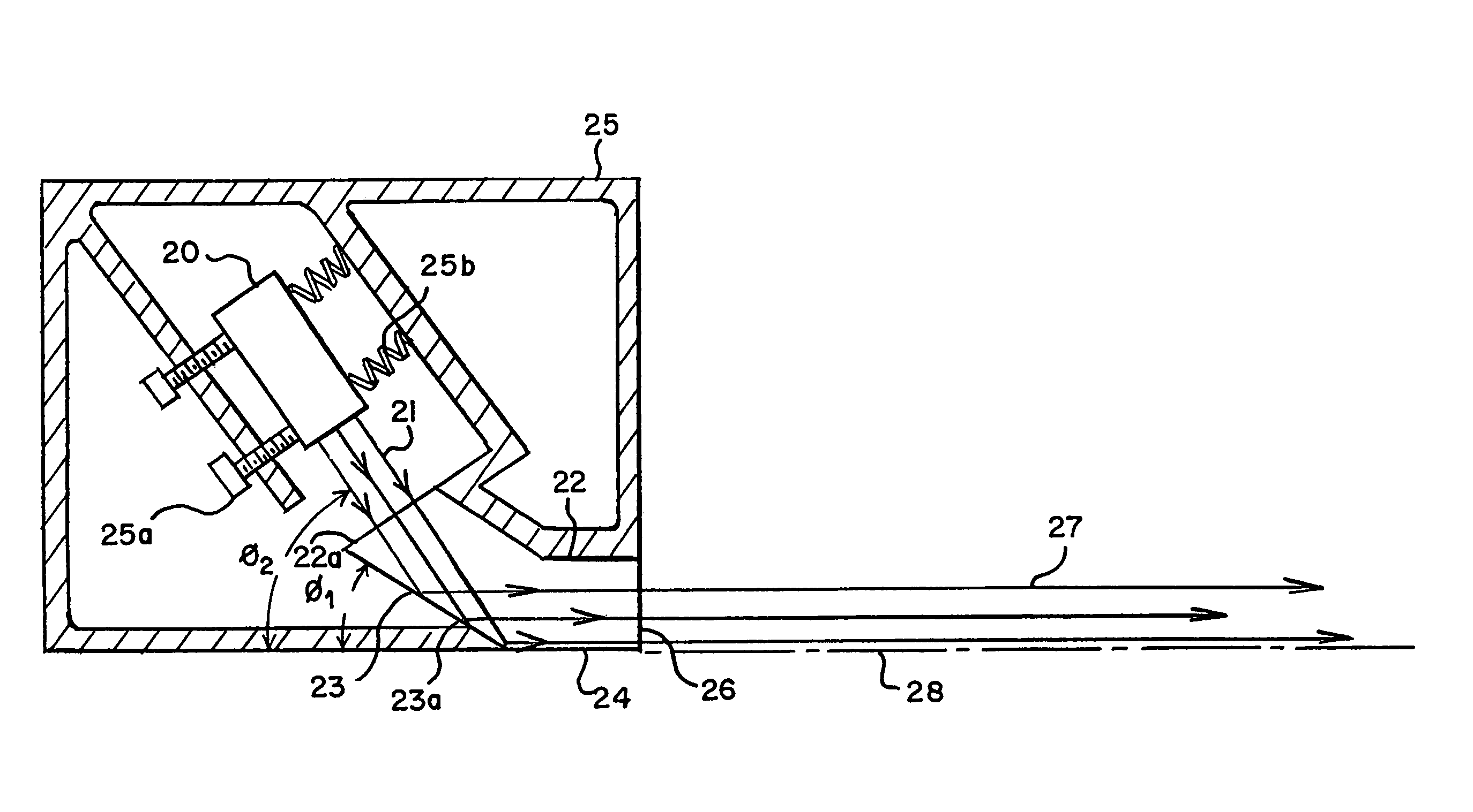
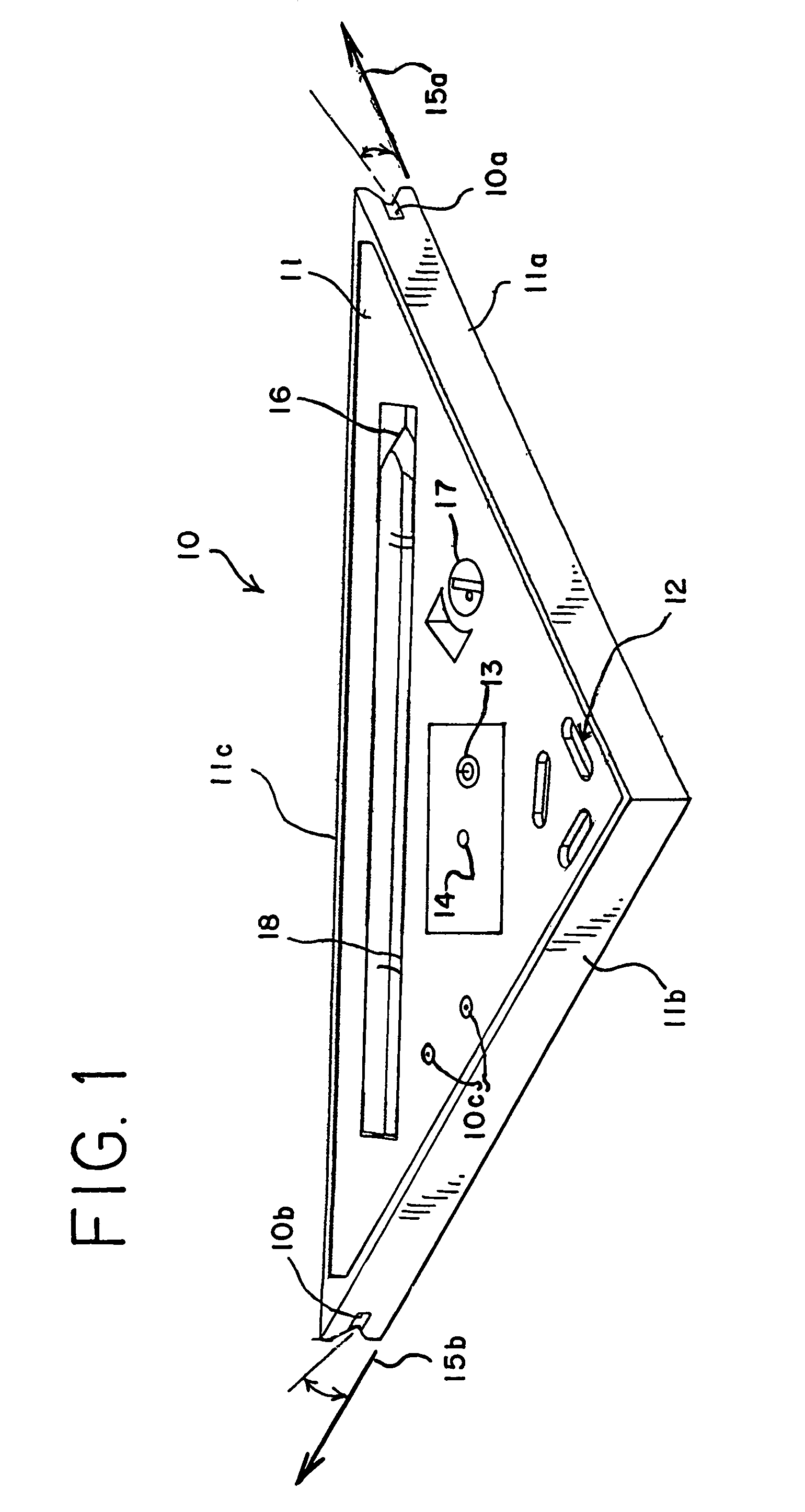
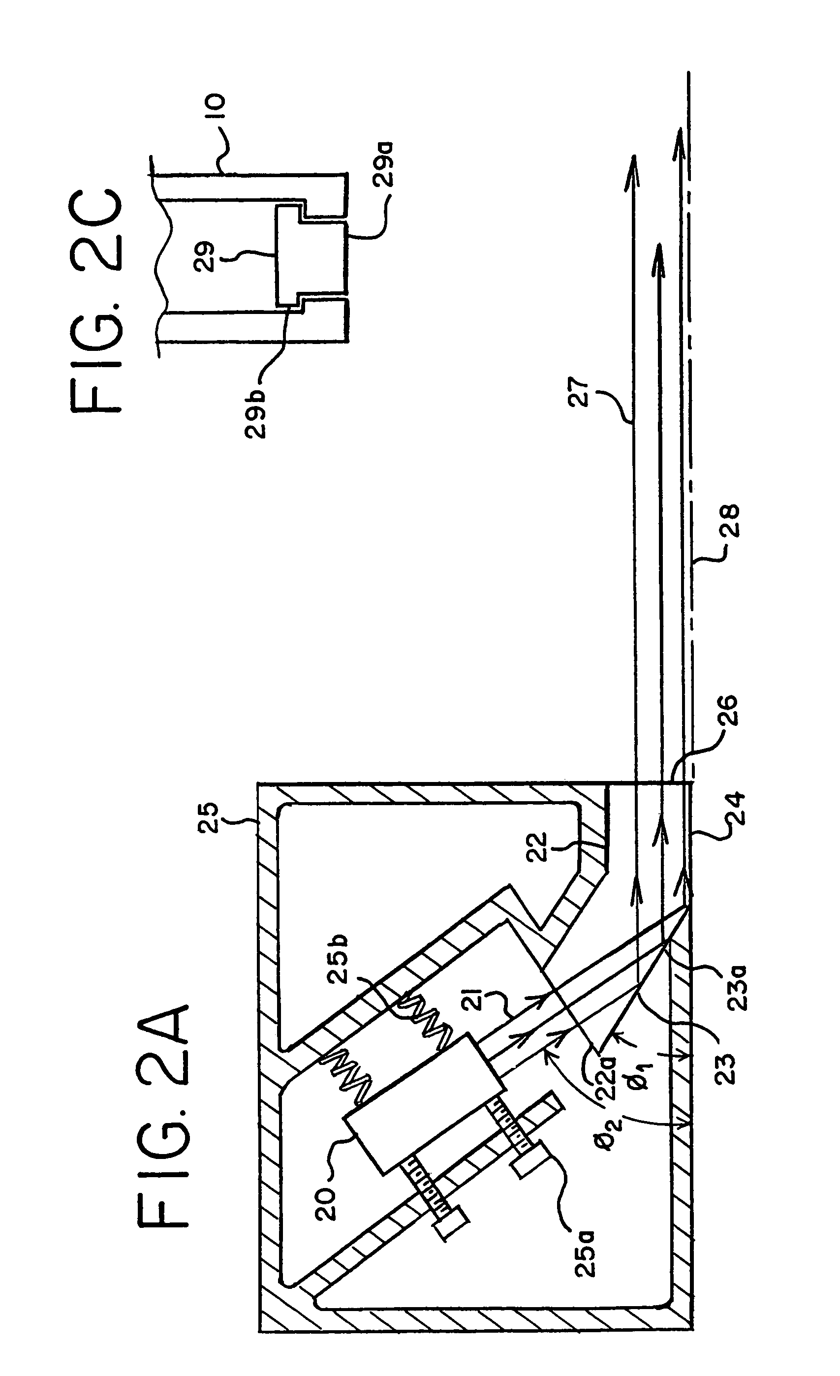
[0028]Embodiments of the present invention overcome the above-mentioned difficulties and provide a virtual extension of a plane of a measuring or aligning device, by using a laser light that extends along an edge or flat surface of the measuring or aligning device. One embodiment of an aligning device according to the present invention is depicted in FIG. 1. A triangular aligning device 10, or “aligning square,” includes two perpendicular flat surfaces 11a, 11b, and generates fan-shaped laser beams 15a, 15b. When the fan-shaped laser beams intersect with surfaces, such as walls or floors, a laser line is generated. Fan shaped laser beams 15a, 15b, are generated adjacent surfaces 11a, 11b.

[0029]Triangular aligning device 10 includes a housing 11, which may be made of molded plastic or metal, or other material that is suitably stiff and strong for use in alignment service. Housing 11 may include one or more bubble levels 12, preferably aligned parallel or perpendicular to the alignme...


PUM


Abstract

A laser reference device includes at least one planar or flat surface and an internal laser light source for generating a laser light beam. A lens inside the device may convert the laser light into a fan-shaped beam, and project the beam adjacent the planar or flat surface of the housing. The fan-shaped beam thus projects along that surface of the housing. If the laser leveling device is placed with the flat surface on a table or floor, for example, the fan-shaped beam will be in a level plane. This allows a user to place the laser leveling device on a surface and generate a laser light to align surfaces or objects, such as objects on a wall.

Description

TECHNICAL FIELD[0001]The technical field of the application relates generally to measuring and aligning devices and specifically to laser measuring and aligning devices.BACKGROUND[0002]Alignment of surfaces is a perennial problem in a variety of fields, ranging from construction to interior decorating. Alignment is necessary for walls that should be perpendicular to a floor, or otherwise plumb. Masonry and brick-laying practitioners are well aware of the importance of plumbed and aligned surfaces and chalk lines. A home interior decorated with pictures and other wall ornamentation has a much better appearance when the ornamentation is aligned, especially with respect to vertical or horizontal alignment. Many mechanical and electrical alignment devices are available, including laser devices. Some of these products are cumbersome, others are not as useful as they could be. Chalk lines, for example, are undesirable for use in finished, interior areas.[0003]Several aspects of alignment-...

Claims


Application Information

Patent Timeline
Patent Type & Authority Patents(United States)
IPC IPC(8): G01C15/00G01C1/10G01C15/12
CPCG01C15/002G01C15/004G01C15/12
Inventor NASH, DEREK J.
Owner BLACK & DECKER INC
Why Eureka
Try Eureka