Angle gauge and method of use

a technology of angle gauge and angle gauge, applied in the field of gauges, can solve the problems of time and cost saving, and achieve the effects of saving time and cost, increasing accuracy, and being easy to calibra

Inactive Publication Date: 2009-02-10
SPIRITO JAMES E
View PDF8 Cites 17 Cited by
  • Summary
  • Abstract
  • Description
  • Claims
  • Application Information

AI Technical Summary

Benefits of technology

[0008]Accordingly, it is an object of the present invention to provide an angle gauge which provides highly visible indication that a correct angle has been achieved. Design features allowing this object to be accomplished include a power supply and light connected in series between a pair of electrically conducting probes attached to a housing having a gauge angle. Advantages associated with the accomplishment of this object include being able to see that the correct angle has been achieved from a distance, along with the associated time and cost saving.
[0009]It is another object of the present invention to provide an angle gauge which is easily calibrated. Design features allowing this object to be accomplished include at least one probe having a probe thread sized to mate with a corresponding threaded bore in a housing. Benefits associated with the accomplishment of this object include increased accuracy, faster angle gauge calibration, and the associated savings in cost and labor.
[0010]It is still another object of this invention to provide an angle gauge which may be used to establish a correct angle in even non-conducting items. Design features enabling the accomplishment of this object include a conductor attached to an object whose angle is to be established, and a pair of electrically conductive probes attached to a housing probe wall on a housing, the housing probe wall and a housing foot defining a gauge angle. An advantage associated with the realization of this object is increased flexibility of use to establish pre-determined angles even in non-conducting items.
[0011]It is still another object of this invention to provide

Problems solved by technology

Advantages associated with the accomplishment of this object include being able to see that the

Method used


Image

  • Angle gauge and method of use
  • Angle gauge and method of use
  • Angle gauge and method of use

Examples


Embodiment Construction

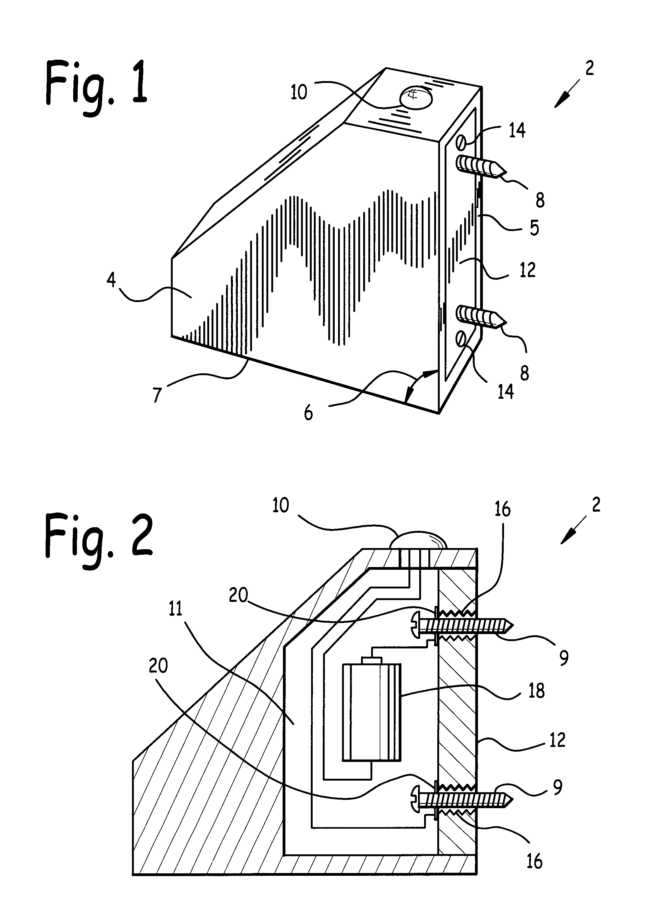
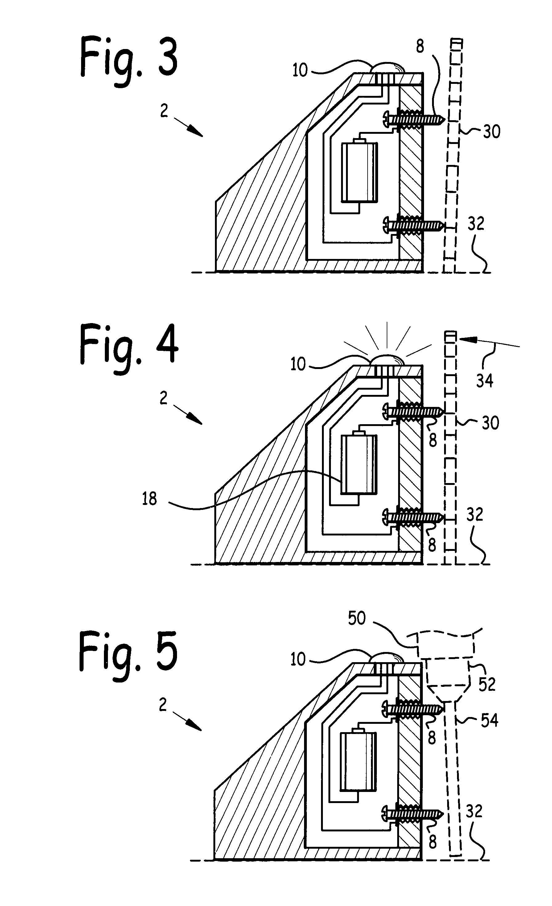
[0024]Referring now to FIG. 1 we observe a front quarter elevated view of angle gauge 2. FIG. 2 is a side cross-sectional view of angle gauge 2. Angle gauge 2 incorporates two electrically conductive probes 8, attached to housing 4. At least one probe 8 is adjustably attached to housing 4, so that angle gauge 2 can be calibrated as illustrated in FIGS. 6 and 7.

[0025]Housing 4 incorporates housing probe wall 5 and housing foot 7. In the preferred embodiment, housing probe wall 5 and housing foot 7 were flat surfaces. Angle gauge 6 is the angle between housing probe wall 5 and housing foot 7, and is substantially equal to the predetermined angle which angle gauge 2 is sized to gauge. In FIGS. 1-7 gauge angle 6 is 90 degrees.

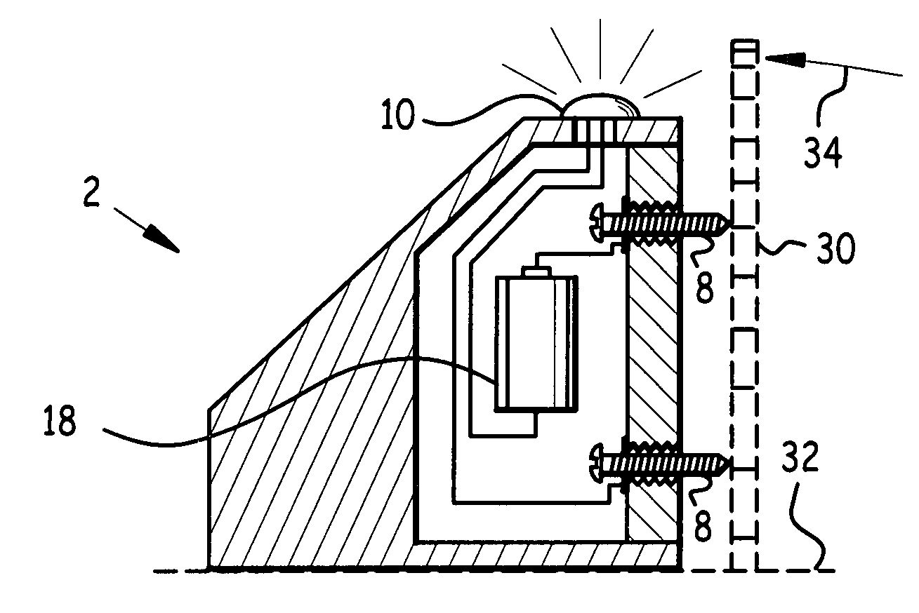
[0026]Light 10 and battery 18 are connected in series between electrically conductive probes 8. Thus, when probes 8 are electrically connected, light 10 illuminates as indicated in FIGS. 4 and 7.

[0027]As may be observed in FIG. 2, in the preferred embodiment at lea...


PUM


Abstract

An angle gauge and method of use. The angle gauge has a housing with a housing probe wall and a housing foot defining a gauge angle. A pair of probes extends from the housing probe wall. A light and a battery are electrically connected in series between the probes. A pre-determined angle between an object and a flat surface can be gauged by placing the angle gauge with its housing foot flat on the flat surface, and then sliding the angle gauge across the flat surface until at least one probe is in electrical contact with the object, and then adjusting the angle of the object relative to the flat surface until both probes are in contact with the object, thereby illuminating the light. A conductor may be attached to non-conducting objects. A method of calibration is disclosed using a calibrated angle.

Description

FIELD OF THE INVENTION [0001]This invention relates to gauges, and in particular to an angle gauge and method of use.BACKGROUND OF THE INVENTION [0002]Many tools require calibration so their cutting media are perpendicular to a work surface supporting the work piece. For example, in order to cut squarely, a table saw blade must be perpendicular to the table. Similarly, a drill press is generally desired to have its drill bit perpendicular to the platform supporting the work piece below the drill. This is achieved by rendering the chuck perpendicular to the platform.EXISTING DESIGNS[0003]A number of approaches have been advanced to adjust the perpendicularity of tools. One procedure is to adjust the blade angle, visually test the angle with a right angle (top and bottom) between the blade and the table, and repeat the procedure until something close to a right angle is achieved, literally through trial and error. This process is time-consuming and inherently inaccurate, and requires ...

Claims


Application Information

Patent Timeline
IPC IPC(8): B23B49/00B23Q17/22
CPCG01B3/56G01B7/31
Inventor SPIRITO, JAMES E.
Owner SPIRITO JAMES E
Why Eureka
Try Eureka