
Reconfigurable direct RF bandpass sampling receiver and related methods

a direct rf bandpass and receiver technology, applied in the direction of digital transmission, amplitude demodulation, pulse technique, etc., can solve the problems of not being entirely effective in receiving and detecting rf signals, and achieve the effect of expanding the maximum frequency rang

Inactive Publication Date: 2009-02-10
L 3 INTEGRATED SYST
View PDF12 Cites 43 Cited by
  • Summary
  • Abstract
  • Description
  • Claims
  • Application Information

AI Technical Summary

Benefits of technology

"The present invention provides a reconfigurable direct RF bandpass sampling receiver that can sample signals in a wide frequency range with a tunable bandpass filter and a single fixed clock. The bandwidth of the filter can be adjusted to optimize search against a variety of signal bandwidths. The receiver can also use a programmable or switched sampling clock to avoid Nyquist sample boundaries and sample arbitrary frequencies. A high-speed analog pre-sampler can be included to extend the maximum frequency range that can be sampled. The invention also includes a method for direct sampling signals with a tunable bandpass filter and a single fixed clock, as well as a system for implementing the invention. The technical effects of the invention include improved performance and flexibility in RF signal analysis and processing."

Problems solved by technology

Each of these prior architectures suffer certain disadvantages and, therefore, have not been entirely effective in receiving and detecting RF signals, particularly in applications requiring large degrees of reconfigurability where the frequency range of interest is very large and extends to many GHz and the instantaneous bandwidth of interest may vary, such as electronic intelligence applications.

Method used


Image

  • Reconfigurable direct RF bandpass sampling receiver and related methods
  • Reconfigurable direct RF bandpass sampling receiver and related methods

Examples


Embodiment Construction

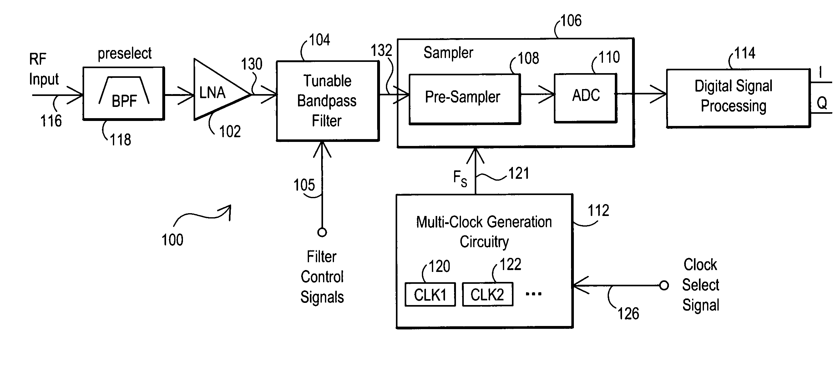
[0010]The present invention provides a reconfigurable direct radio frequency (RF) bandpass sampling receiver that provides direct RF sampling of an input signal spectrum passed through a bandpass filter that is tunable over a wide frequency range of interest and which is sampled based on the bandwidth of the filter rather than the bandwidth of the total frequency range of interest. The bandwidth of the filter may further be variable to provide for optimized search against a variety of signal bandwidths. The reconfigurable direct RF bandpass sampling receiver may be implemented with a single fixed clock for applications where the signals of interest lie in adjacent non-overlapping frequency channels. For applications requiring arbitrary tuning, the reconfigurable direct RF bandpass sampling receiver can also use a programmable or switched sampling clock to avoid the Nyquist sample boundaries that occur with bandpass sampling and thus provide sampling of arbitrary frequencies. A high-...


PUM


Abstract

Reconfigurable direct radio frequency (RF) bandpass sampling receivers are disclosed that provide direct RF sampling of an input signal spectrum passed through a bandpass filter that is tunable over a wide frequency range of interest and that is sampled based on the bandwidth of the filter rather than the bandwidth of the total frequency range of interest. The bandwidth of the filter may further be variable to provide for optimized search against a variety of signal bandwidths. The reconfigurable direct RF bandpass sampling receiver may be implemented with a single fixed clock for applications where the signals of interest lie in adjacent non-overlapping frequency channels. For applications requiring arbitrary tuning, the reconfigurable direct RF bandpass sampling receiver can also use a programmable or switched sampling clock to avoid the Nyquist sample boundaries that occur with bandpass sampling and thus provide sampling of arbitrary frequencies. A high-speed analog pre-sampler may be included to extend the maximum frequency range that can be sampled.

Description

RELATED APPLICATIONS[0001]This subject matter of this Application is related in part to the subject matter described in concurrently filed application Ser. No. 11 / 247,314, entitled “SWEPT BANDPASS FILTER FREQUENCY MODULATED CONTINUOUS WAVE (FMCW) RECEIVER AND RELATED METHOD,” which is hereby expressly incorporated by reference in its entirety.TECHNICAL FIELD OF THE INVENTION[0002]This invention relates to receiver architectures for the efficient sampling of radio frequency (RF) signals and, more particularly, to receiver architectures for the efficient sampling of signals over a wide frequency range of interest.BACKGROUND[0003]A wide variety of signals and related protocols exist for the use of radio frequency (RF) signals in communication systems and other devices, such as radar systems. In some applications, it is desirable to determine or confirm the existence of RF signals and accurately measure their parameters. RF signals of interest, however, can occur across a wide range of ...

Claims


Application Information

Patent Timeline
Patent Type & Authority Patents(United States)
IPC IPC(8): H03K9/00H04L27/00
CPCH04B1/0003H04B1/0007H04B1/28H04L7/0338
Inventor FUDGE, GERALD L.
Owner L 3 INTEGRATED SYST
Learn More