
Bench scale apparatus to model and develop biopharmaceutical cleaning procedures

a biopharmaceutical and bench-scale technology, applied in the direction of chemistry apparatus and processes, instruments, material analysis, etc., can solve the problems of insufficient exemplification of conditions in the cleaning procedures typically used on the coupons, time-consuming and impractical production equipment, and difficult questions affecting the fundamental components of cleaning details

Inactive Publication Date: 2009-02-17
WYETH RES IRELAND LTD
View PDF3 Cites 0 Cited by
  • Summary
  • Abstract
  • Description
  • Claims
  • Application Information

AI Technical Summary

Benefits of technology

The apparatus enables efficient development and validation of cleaning procedures by accurately simulating full-scale CIP conditions, reducing downtime and resource expenditure, and providing a scientifically justifiable method for selecting worst-case soiling solutions, thereby optimizing cleaning cycles and minimizing manufacturing downtime.

Problems solved by technology

The proper development, modeling and improvement of biopharmaceutical cleaning procedures are often time-consuming and impractical when production equipment is otherwise in use.
However, the cleaning procedures typically used on the coupons do not sufficiently exemplify the conditions and phases of a Cleaning-in-Place (CIP) cycle within a production vessel.
But in designing a cleaning cycle for new or not well-understood soiling solutions in biopharmaceutical manufacturing processes, the difficult questions concern the fundamental components of cleaning details.
Regulatory agencies continually inquire about cleaning programs, requiring an immense expenditure of resources and capital by commercial biopharmaceutical companies simply to document cleaning procedures.
Of these, process modeling has been the least investigated as to its efficiency and effectiveness.
Biopharmaceutical drug substances are often in short and expensive supply.
The problem with this approach is that the soaking method may inaccurately represent the ratio of cleaning solution to soil per surface area.
Furthermore, static soaking does not accurately reproduce the representative sheeting or cascading action that interior surface vessels receive when CIP cleaning chemicals are introduced via devices such as spray balls and spray wands.
When encountering a process solution for the first time, it may be difficult to determine suitable cleaning contact times, temperatures, chemical concentrations and external energies or action necessary to effectively and efficiently remove unwanted soil from manufacturing process equipment.
However, since this can be a long and arduous process, a suitable model system is paramount in maximizing the feasibility of proper development by minimizing manufacturing equipment downtime.
The choice of a proper manufacturing solution, or soiling solution from the cleaning validation perspective, on which to conduct cleaning development studies may either be a rather simple issue of immediate need to validate the cleaning of a specific soil, or it may be a more complex issue that requires more discussion and scientific logic to determine.
In biotechnology processes where numerous culture media and purification buffers are the norm for manufacturing a single product, the choice of a cleaning validation “worst case” challenge soil is typically imprecise, or one of historical precedent without much scientific analysis.
New biopharmaceutical manufacturing processes may be even more difficult to assess since there may be little empirical information regarding which solutions historically present the greatest cleaning challenge.
However, in the case of an established multi-product / multi-soil piece of equipment or new biopharmaceutical manufacturing processes, the choice of a worst case challenge soil poses more of a quandary.
While it may be preferable to validate the cleaning of every soil to enter that equipment, resources and time greatly limit the number of validation runs that can be realistically conducted.
Furthermore, for new manufacturing processes situations, not all process solutions may be enumerated at the time the cleaning validation is performed.

Method used


Image

  • Bench scale apparatus to model and develop biopharmaceutical cleaning procedures
  • Bench scale apparatus to model and develop biopharmaceutical cleaning procedures
  • Bench scale apparatus to model and develop biopharmaceutical cleaning procedures

Examples


example 1

[0071]The Last2Rinse was implemented to investigate the cleanability of various soils from several commonly used MOC coupons: Stainless Steel (SS), Glass, Polymethylpentene (PMP), Silicone, Acrylic, TEFLON (polvtetrafluorethvlene), Polypropylene (PolyPro), and Ethylene-Propylene-Diene Monomer (EPDM). Triplicate coupons of these MOC were soiled with 1 ml of six different soiling solutions. These soiling solutions were allowed to dry on the coupons for eight hours in an incubator at 37° C. To clean the MOC coupons, five cleaning cycles, A though E, were implemented (Table 3). Coupons were exposed to a maximum of 300 seconds of each cleaning cycle; each cycle was more aggressive than the previous one. A calibrated stopwatch was used to time the cycles. When coupons were visually clean, they were removed from the apparatus and swabbed for residual TOC. If coupons were not deemed visually clean upon a completion of a 300 second cycle, they were exposed to the next most aggressive cleanin...

example 2

Empirical Assessment of “Worst Case” Challenge Soil Selections

[0075]The results in FIG. 5 also include an empirical demonstration of choosing a cleaning validation “worst case” challenge soiling solution. The soiling solutions in this experiment were chosen on the basis of component number, complexity, concentration, solubility and viscosity. These solutions were given a cleanability rating (i.e., Total Matrix Value) utilizing the semi-quantitation matrix approach described above (see Table 4). Table 5 summarizes the soil types investigated with respect to their total matrix value and observed cleaning times. The results clearly indicate that the low component buffer with a highly hydrophobic (non-aqueous organic) component took the longest time to come visually clean on any MOC surface. The high component / high concentration media was the next most difficult to clean, followed by the low component / high concentration buffer. The low component / low concentration buffer and low componen...

example 3

Sample Calculation of an Example Soil Using the Challenge Semi-Quantitation Matrix

[0077]Buffer XYZ from “Acme” Buffer Suppliers has the following components:

[0078]

.020 M MESAqueous Soluble Organic(2.62 g / L MES-acid + 1.45 g / LMES-base = 4.07 g / L)0.020 M CaCl2Divalent Salt(2.94 g / L)0.1% V-Tween-80Aqueous Soluble Organic(1.0 mL / L × a density of 1.1 g / mL =1.1 g / L)1 M NaClMonovalent Salt (58.4 g / L)(58.4 g / L)0.020 M L-HistidineAmino Acid (3.1 g / L)(3.1 g / L)

Both MES and V-Tween-80 are categorized as “Aqueous Soluble Organics” and therefore their gram weights are added together (4.07 g / L MES+1.1 g / L Tween=5.17 g / L or ≧4 g / L of Aqueous Soluble Organics in the Concentration Dependent Multiplier). Acme calls for bringing the pH of the solution to pH 6.0 with 2.0 mL / L of concentrated HCl, therefore, an Acid component is also accounted for in the Matrix. The Matrix, with highlighted cells showing the place of each component on the table, is shown in Table 6; the final semi-quantitation value is B...


PUM

PropertyMeasurementUnit
angleaaaaaaaaaa
temperatureaaaaaaaaaa
pressuresaaaaaaaaaa

Abstract

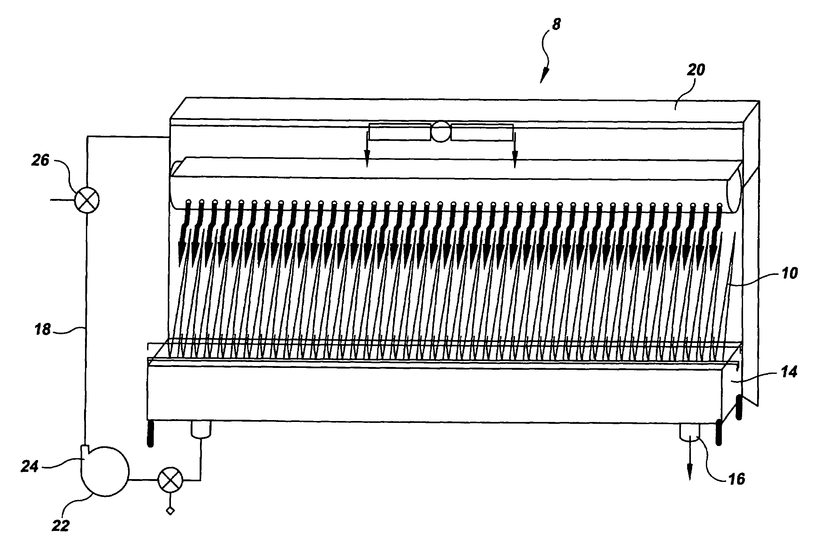
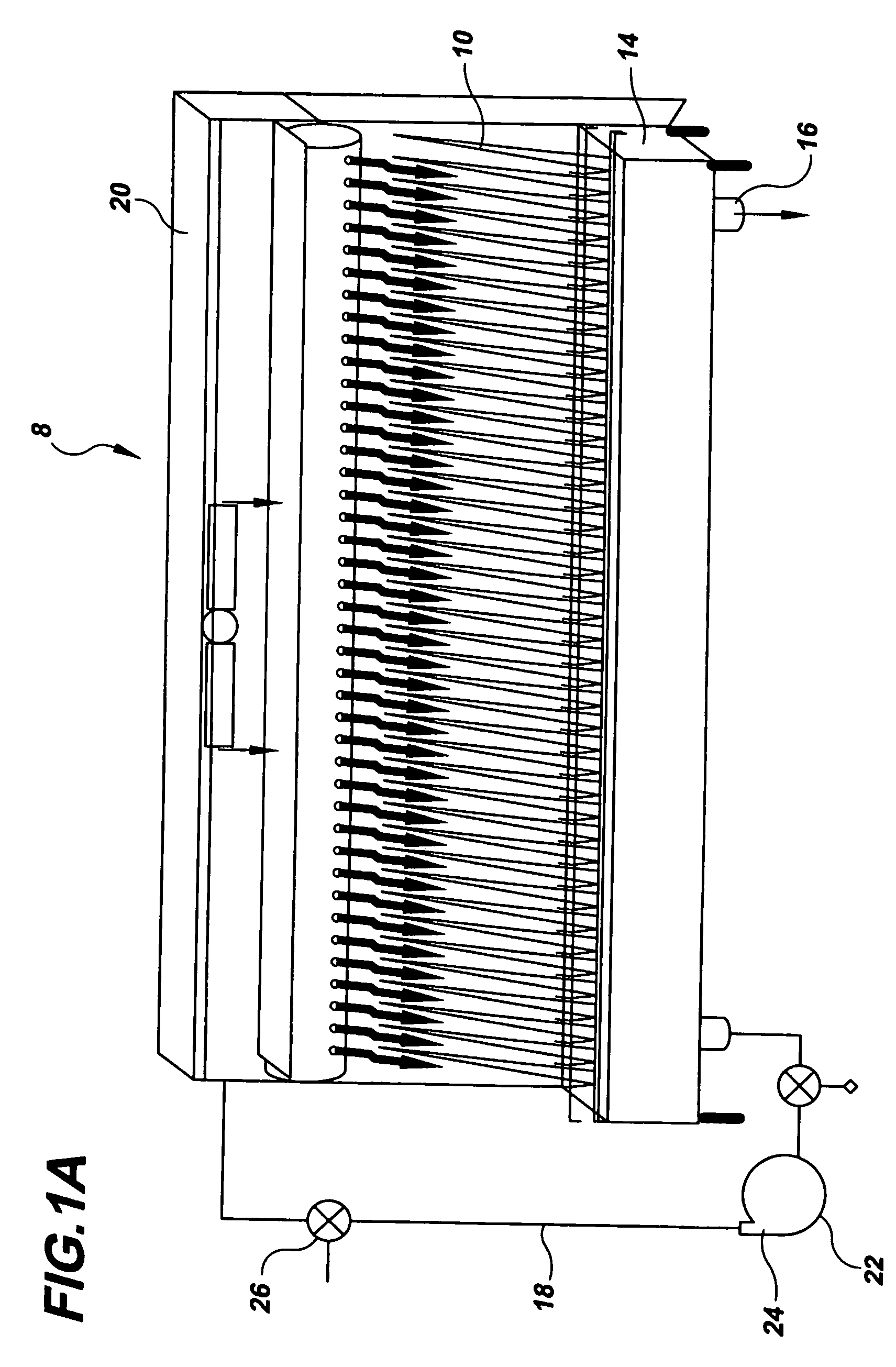
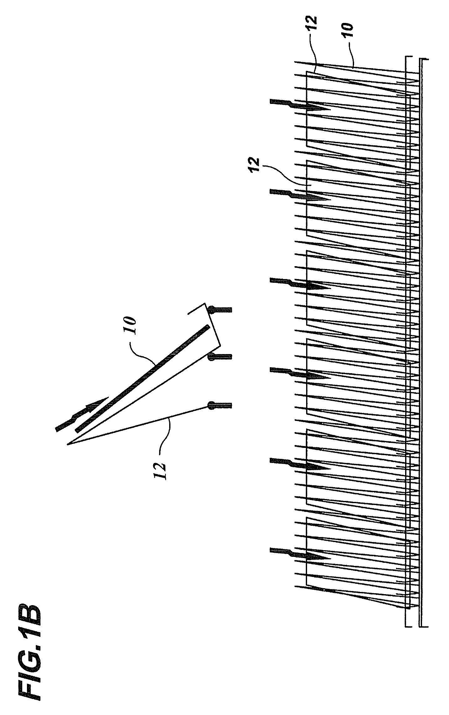
An apparatus for testing a cleaning procedure for a material. The apparatus includes a rack having a seat configured to retain a plurality of test coupons at a predetermined angle, an upper tray that distributes a solution along the lines of the rack, a lower tray for receiving solution passed over coupons disposed on the rack, a meter that gauges a flow rate of the solution, a thermostatic heater adapted to bring the solution to a predetermined temperature, and a variable speed pump that directs the solution from a reservoir to the upper tray.

Description

[0001]This application claims the priority of U.S. Provisional Application No. 60 / 618,554, filed Oct. 12, 2004, the entire contents of which are incorporated herein by reference.FIELD OF THE INVENTION[0002]This invention pertains to the identification and evaluation of solutions for removing biopharmaceutical soil from materials.BACKGROUND OF THE INVENTION[0003]The proper development, modeling and improvement of biopharmaceutical cleaning procedures are often time-consuming and impractical when production equipment is otherwise in use. Laboratory studies on coupons of representative biopharmaceutical manufacturing materials of construction (MOC) have long been the model on which cleaning regimens have been tested. Coupons, in and of themselves, are adequate models of the surfaces that need to be cleaned. However, the cleaning procedures typically used on the coupons do not sufficiently exemplify the conditions and phases of a Cleaning-in-Place (CIP) cycle within a production vessel....

Claims


Application Information

Patent Timeline
Patent Type & Authority Patents(United States)
IPC IPC(8): G01N37/00B08B3/08
CPCB08B3/04
Inventor CANHOTO, ALFREDO J.AZADAN, ROD J.PUTNAM, JOHNKREUZE, MICHAELWILLIAMS, BRIANNOBLES, KRISTENCHAPMAN, JEFFBARRETT, KELLI
Owner WYETH RES IRELAND LTD
Learn More