Aircraft with rotor vibration isolation

a technology of rotor blades and airframes, which is applied in the field of rotor aircraft, can solve the problems of increased complexity and weight, significant ride vibration or disturbance felt by passengers, and use of more than two blades on the rotor, and achieves good dampening characteristics

Active Publication Date: 2009-02-17
JAUNT AIR MOBILITY LLC
View PDF15 Cites 31 Cited by
  • Summary
  • Abstract
  • Description
  • Claims
  • Application Information

AI Technical Summary

Benefits of technology

[0009]One method of accomplishing this movement is to use elastomeric bearings with good dampening characteristics located on either side of the gearbox on the crossover shaft connecting a propeller on each side of the fuselage. The elastomeric bearings mount to the support arms described above and allow the rotor shaft to pivot fore and aft and tilt side to side due to the softness of the elastomeric bearings, allowing the rotor to move horizontally and vertically as required to isolate rotor oscillations / vibrations.

Problems solved by technology

This transfer, however, can be responsible for significant ride vibrations or disturbances felt by the passengers.
However, in addition to the increased complexity and weight from using more than two blades, there is another significant drawback to using more than two blades on the rotor, which is the inability to have compact storage.
This increases weight and complexity.

Method used


Image

  • Aircraft with rotor vibration isolation
  • Aircraft with rotor vibration isolation
  • Aircraft with rotor vibration isolation

Examples


Embodiment Construction

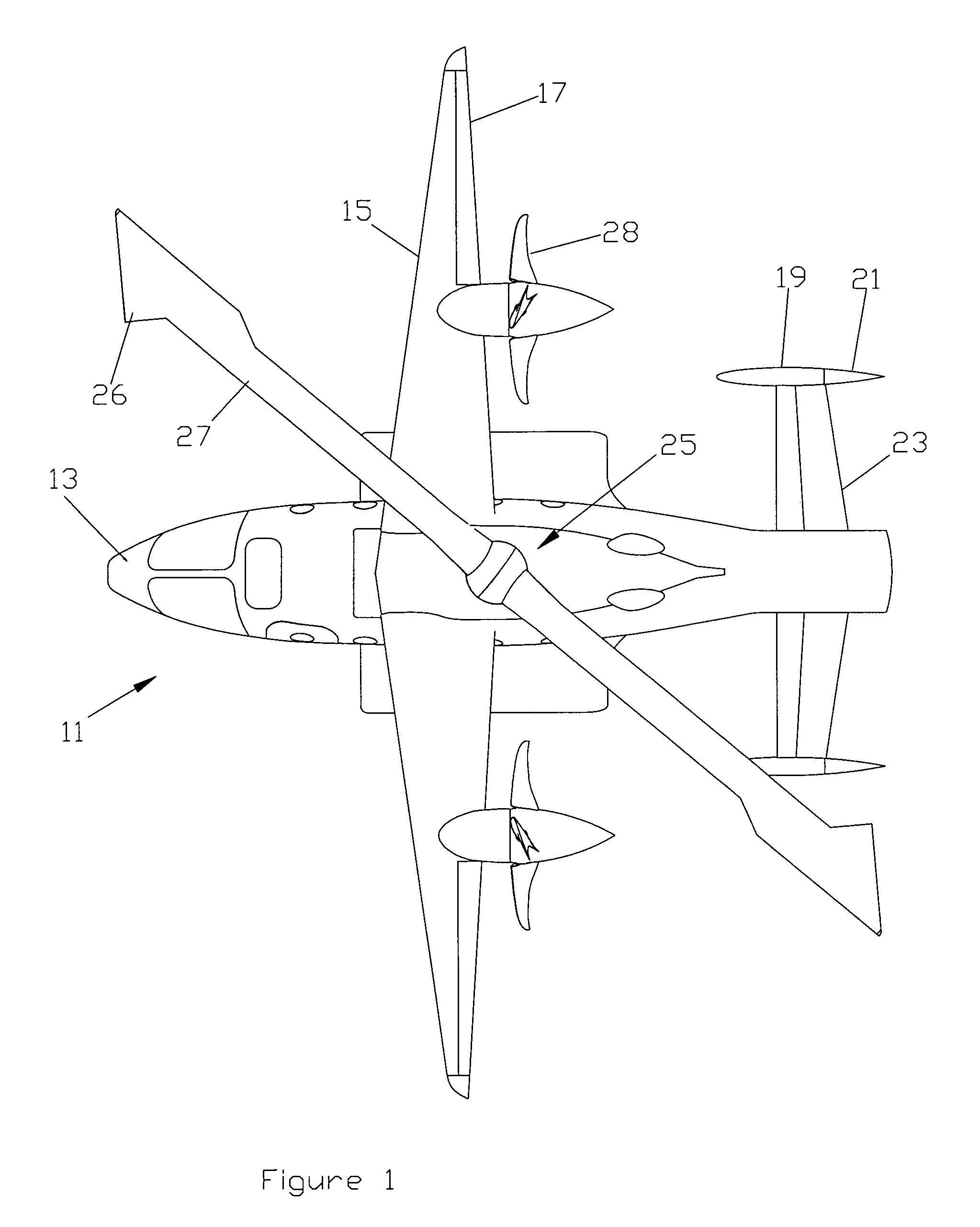
[0017]Referring to FIG. 1, an example of a rotor aircraft 11 is shown. Aircraft 11 has a fuselage 13 and two fixed wings 15. Each wing 15 has an aileron 17 in this embodiment. Aircraft 11 also has two vertical stabilizers 19, each located immediately forward of a movable rudder 21. A movable horizontal stabilizer, referred to as a stabilator 23, is located between vertical stabilizers 19.

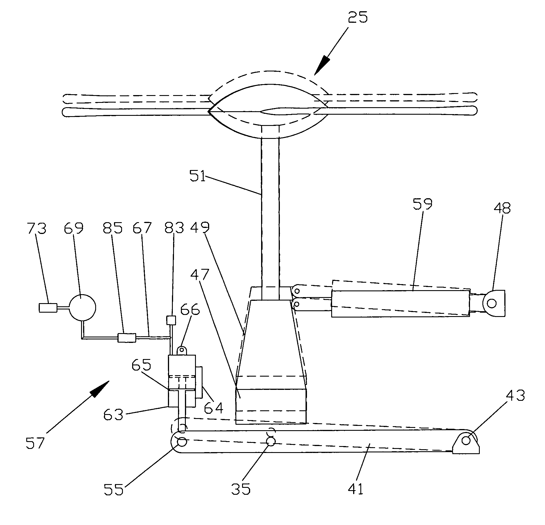
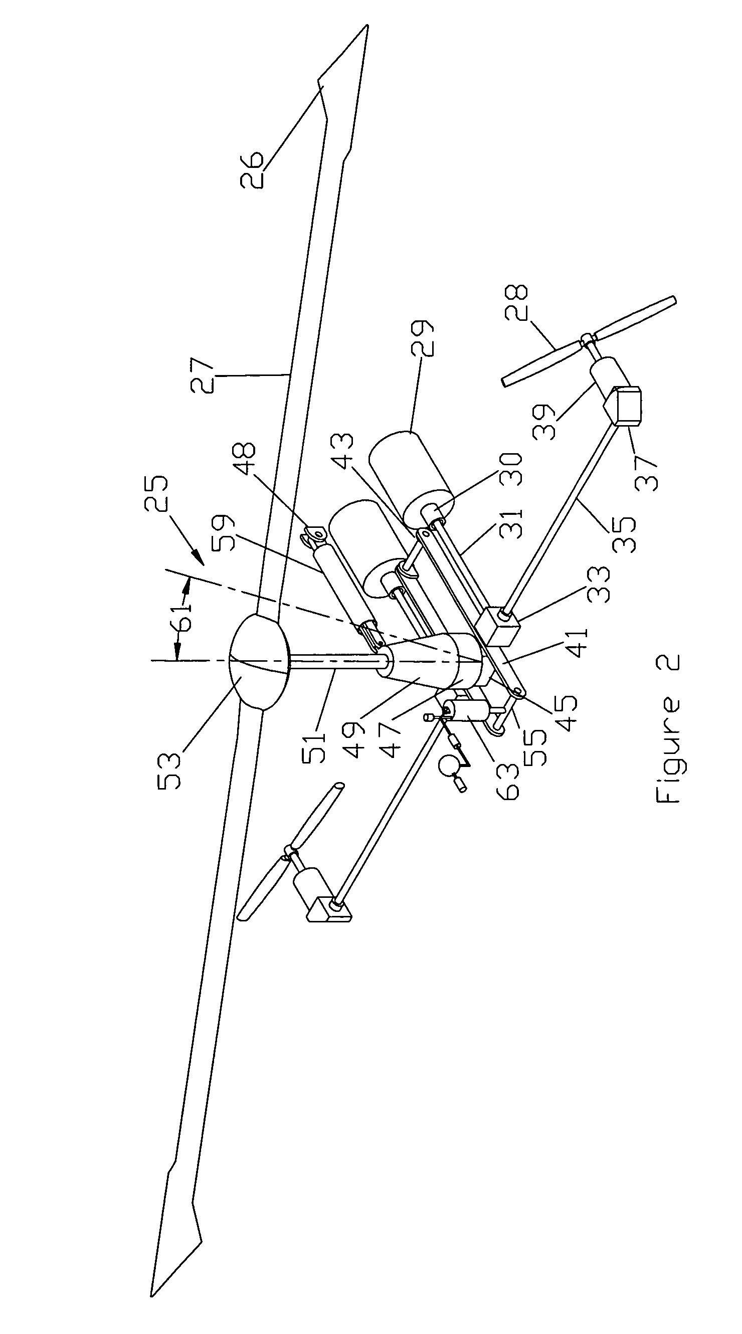
[0018]A rotor 25 is mounted to the upper side of fuselage 13. Rotor 25 has two blades 27 in this embodiment, but it could have more than two. Each blade 27 has tip weights 26 for providing inertia for jump takeoff and stabilization at slow rotor speeds. Aircraft 11 has two propellers 28 in this embodiment, each mounted to one of the wings 15. Preferably propellers 28 provide differential thrust to counter the torque created by rotor 25 when driven during flight, particularly when hovering. Aircraft 11, alternately, could have a single propeller mounted along the longitudinal axis of fuselage 13. In ...


PUM


Abstract

A rotor aircraft has a fuselage with a rotor mounted above by a rotor shaft. An arm is pivotally engaged with a lower portion of the rotor shaft and pivotally engaged with the fuselage, enabling the rotor to move with little restriction vertically and horizontal in all directions relative to the fuselage as the rotor rotates in order to isolate rotor oscillations. An infinitely variable air spring is used to counter vertical and fore and aft loads. Damping in the form of elastomeric materials, piston seal friction, and fluid flow through an orifice may be added as required.

Description

CROSS REFERENCE TO RELATED APPLICATION[0001]This application claims the benefit of provisional application Ser. No. 60 / 628,371 filed Nov. 16, 2004.FIELD OF THE INVENTION[0002]This invention relates in general to rotor aircraft, and in particular to an assembly for isolating the rotor vertical, horizontal and side-to-side oscillations from the airframe.BACKGROUND OF THE INVENTION[0003]One type of rotor aircraft, referred to as a gyroplane, has a fuselage, wings, rotor and a propeller. For a jump takeoff, the rotor is pre-rotated to an overspeed while the aircraft is still on the ground. The propeller also is rotating. The pilot releases the brakes and increases the collective pitch on the propeller and rotor to cause the aircraft to lift from the ground. As the aircraft picks up forward speed, the wings assume more of the load and the rotor is tilted forward, decreasing the rotor speed and decreasing the load assumed by the rotor. At cruise speed, the rotor turns slowly while the win...

Claims


Application Information

Patent Timeline
Patent Type & Authority Patents(United States)
IPC IPC(8): B64C27/00
CPCB64C27/001B64C27/025B64C27/12B64C27/26B64C2027/004
Inventor CARTER, JR., JAY W.
Owner JAUNT AIR MOBILITY LLC
Why Eureka
Try Eureka