Spherical enclosure for a camera

a camera and enclosure technology, applied in the field of spherical lens enclosures, can solve the problem of very limited tilt range of devices

Inactive Publication Date: 2009-02-17
CRITERION TECH
View PDF16 Cites 9 Cited by
  • Summary
  • Abstract
  • Description
  • Claims
  • Application Information

AI Technical Summary

Benefits of technology

[0015]The present invention provides a generally spherical lens enclosure that is formed by bonding a plurality of optical sections. A minimal seam joining the optical sections may be located at any point on the sphere in relation to the mounting location. In making the seams at the juncture of the optical sections, the purpose is to maximize mechanical strength while minimizing the optical obstruction that may be induced by the seam.
[0017]It is therefore an object of the present invention to allow for the camera to be mounted in a spherical lens enclosure such that the optical center of the camera is coincident with the geometric center of the spherical enclosure throughout all angles of camera pan and tilt, minimizing distortion of the camera image. It is a further object of the present invention to provide a spherical camera enclosure that obscures the camera position. It is a further object to allow for an interior coating of the enclosure to further obscure the camera position. It is a further object to allow for the placement of lens-like areas of the enclosure by shaping the interior and / or exterior surface of the enclosure. It is a further object to provide an enclosure that can be manufactured by bonding two or more sections into a spherical enclosure, where the seam between the sections can be positioned to minimize its interference with viewing areas of interest and where the individual sections may be made utilizing dissimilar manufacturing techniques and / or materials.
[0019]It is a further object to provide an interior liner for the spherical enclosure that cloaks the position of the camera and can be inserted through an opening in the enclosure and then expanded once inserted.

Problems solved by technology

These devices have a very limited tilt range and can view areas from directly in the center of the hemispherical enclosure to the perimeter of the enclosure.

Method used


Image

  • Spherical enclosure for a camera
  • Spherical enclosure for a camera
  • Spherical enclosure for a camera

Examples


Embodiment Construction

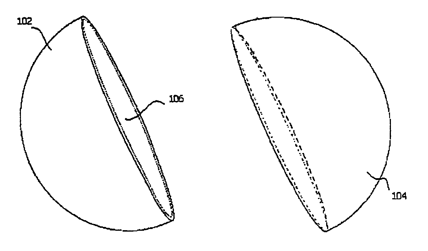
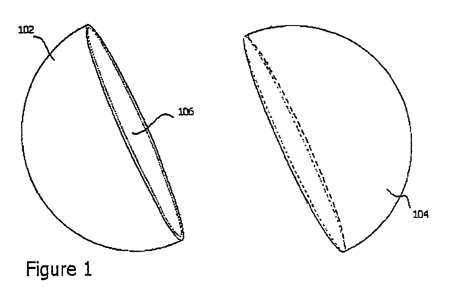
[0020]In the following description numerous specific details are set forth in order to provide a more thorough understanding of the present invention. It will be apparent to one skilled in the art that the present invention may be practiced without these specific details. In other instances, well-known features have not been described in order to not obscure the invention. Referring now to the drawings and to that embodiment of the invention here presented by way of illustration, FIG. 1 illustrates two hemispherical shaped optical sections 102-104 that are formed to define a spherical enclosure with an internal cavity 106 that allows a camera or similar device to be inserted into the internal cavity. The optical sections 102-104 are molded or cast of a polymer material while holding close manufacturing tolerances. The materials used may vary so long as they remain useful with respect to the requirements of the imaging equipment that will be located within the cavity 106 and obtain a...


PUM


Abstract

A spherical enclosure for a camera, has in some examples, an optically transmitting wall, a highly-reflective external surface, a coated internal surface, a collapsible internal lining, and a support tube. The wall may have a region of varying wall thickness providing a lens. The collapsible internal liner is made of a material that obscures the camera's silhouette, and is inserted through an opening in the wall while folded, and then expands into position. The inner surface of the enclosure may be coated with a material that reduces internal reflections. The camera, when mounted in the enclosure has the optical center of the camera coincident with the geometric center of the spherical enclosure, so that distortion of the camera image is minimized.

Description

FIELD OF THE INVENTION[0001]This invention relates generally to surveillance camera enclosures and housings, and more specifically with a spherical lens enclosure that provides the benefits of hemispherical lens applications with additional viewing and covert capabilities.DESCRIPTION OF RELATED ART[0002]It is very common to use closed circuit television cameras for video surveillance. In many applications, it is necessary to mount the camera inside an enclosure to protect the device from weather, tampering, and provide an obscure means of pointing a camera without visible detection. In such situations, an optically clear lens enclosure is typically utilized to minimize video degradation.[0003]The prior art discloses a hemispherical polymer lens enclosure. These devices employ fixed or motorized platforms that pan and tilt a camera, allowing the camera to be moved and aimed at various locations in the viewing area. These devices have a very limited tilt range and can view areas from ...

Claims


Application Information

Patent Timeline
Patent Type & Authority Patents(United States)
IPC IPC(8): G03B17/00G03B17/02G03B17/08G03B17/56G03B39/00
CPCG03B17/08G03B17/56G03B17/565
Inventor MULVEY, CHRISTOPHER BLAIRMULLINS, RUSSELL HENRYHENRY, WILLIAM ROLFE
Owner CRITERION TECH
Why Eureka
Try Eureka