
Polymeric monolithic capacitor

a polymer monolithic capacitor and polymer technology, applied in the direction of wound capacitors, fixed capacitor details, fixed capacitors, etc., can solve the problems of limited degree to which the thickness of the pp film can be reduced, mfc capacitors, and film thickness must be adequate, so as to minimize the electrical resistivity of the capacitor termination, the effect of maximizing mechanical strength

Inactive Publication Date: 2020-06-18
POLYCHARGE AMERICA INC
View PDF6 Cites 0 Cited by
  • Summary
  • Abstract
  • Description
  • Claims
  • Application Information

AI Technical Summary

Benefits of technology

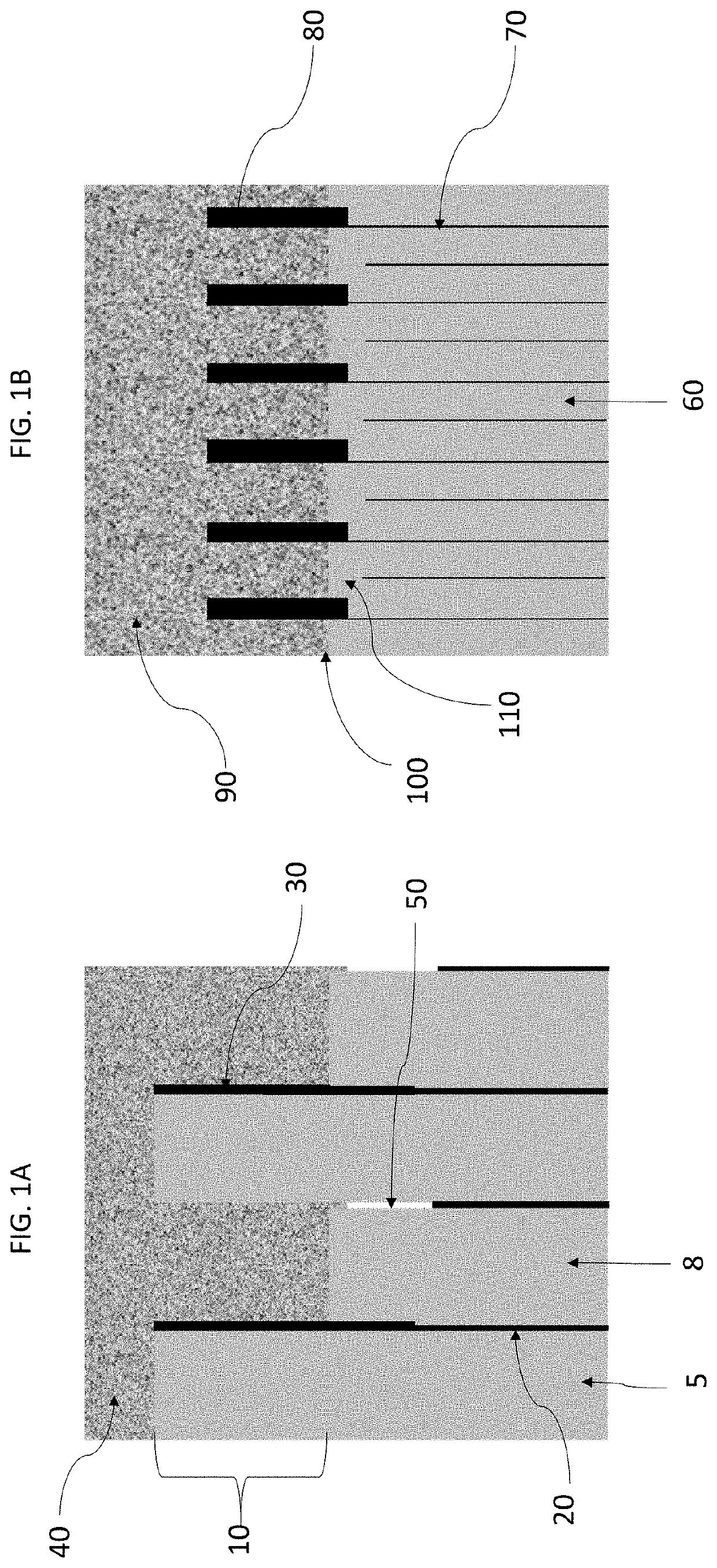
The invention provides a metallized polymer capacitor that is created in a vacuum and includes layers of polymer and metallized electrodes. The capacitor has two electrodes, one of which has a thicker portion in the active area and a thinner portion in the termination area. The thinner portion has low resistance to allow for a self-healing process. The capacitor has mechanical strength and low electrical resistivity.

Problems solved by technology

A major limitation of MFC capacitors is that the film must be thick enough for adequate uniformity and strength to be further handled for metallization, slitting, and winding into capacitors.
However, the degree to which the thickness of the PP film can be reduced is limited by the film-manufacturing process, and the resulting thickness of PP films is typically no less than about two microns.
Therefore, lower voltage applications (such as those specified at 25 V-50 V) that require large capacitance and small size cannot use PP film capacitors.
Metallized PP capacitors that are almost exclusively used in such DC-link applications have an operating temperature limited to 105° C. with significant derating in voltage, ripple current and capacitor lifetime and, furthermore, PP capacitors are relatively large and costly.
Since new power semiconductor devices are now operating at higher temperatures and frequencies, the heat load to the capacitors is increased, thereby imposing additional constraints on the operating conditions of a given capacitor.

Method used


Image

  • Polymeric monolithic capacitor
  • Polymeric monolithic capacitor
  • Polymeric monolithic capacitor

Examples


Embodiment Construction

[0024]This invention is directed at fabrication of a polymeric monolithic capacitor possessing self-healing properties that prevent catastrophic failure of the capacitor (and that may result, instead, only in a benign failure mode), high temperature stability, resistance to degradation in high-temperature and high-humidity environments, and ability to handle high-ripple currents, and extreme thermomechanical environments.

[0025]The term “polymer monolithic capacitor” (PMC) is used to describe a capacitor that originates as a multilayer composite (or “mother capacitor”) material produced or formed around a rotating drum in the form of thousands of polymer dielectric and electrode layers. The mother capacitor material is removed from the drum and is processed into individual capacitors, via a series of process steps that include pressing the mother capacitor material, segmentation of the pressed material into individual capacitors, etching of the electrodes at the cut edges to prevent ...


PUM

PropertyMeasurementUnit
glass transition temperatureaaaaaaaaaa
sheet resistanceaaaaaaaaaa

Abstract

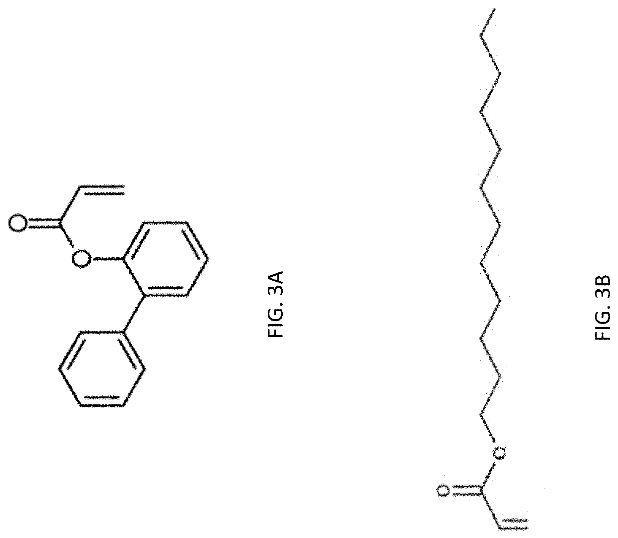
Prismatic polymer monolithic capacitor structure that includes multiple interleaving radiation-cured polymer dielectric layers and metal layers. Method for fabrication of same. The chemical composition of polymer dielectric and the electrode resistivity parameters are chosen to maximize the capacitor self-healing properties and energy density, and to assure the stability of the capacitance and dissipation factor over the operating temperature range. The termination electrode that extends beyond the active capacitor area and beyond the polymer dielectric layers has a thickness larger than that used industrially to provide resistance to thermomechanical stress. The glass transition temperature of the polymer dielectric is specifically chosen to avoid mechanical relaxation from occurring in the operating temperature range, which prevents high moisture permeation (otherwise increasing a dissipation factor and electrode corrosion) into the structure. The geometry and shape of the capacitor are appropriately controlled to minimize losses when the capacitor is exposed to pulse and alternating currents.

Description

CROSS-REFERENCE TO RELATED APPLICATIONS[0001]This application is a continuation in part of U.S. patent application Ser. No. 16 / 035,475 filed on Jul. 13, 2018 and now published as US 2018,0342353, which is a continuation-in-part of U.S. patent application Ser. No. 15 / 625,282, filed on Jun. 16, 2017 (now U.S. Pat. No. 10,102,974), which in turn is a continuation-in-part of U.S. patent application Ser. No. 15 / 483,780, filed on Apr. 10, 2017 (now U.S. Pat. No. 10,347,422)), which is a continuation of U.S. patent application Ser. No. 14 / 668,787 filed on Mar. 25, 2015 (now U.S. Pat. No. 9,711,286). The disclosure of each of the above-mentioned applications is incorporated by reference herein.TECHNICAL FIELD[0002]The present invention relates generally to polymeric monolithic capacitors and, in particular, to capacitors produced using a non-thermoplastic submicron thick polymer dielectric, chemically configured to maximize self-healing and minimize moisture absorption, along with aluminum ...

Claims


Application Information

Patent Timeline
Patent Type & Authority Applications(United States)
IPC IPC(8): H01G4/14H01G4/30H01G4/232H01G4/005C08F122/14H01G4/12
CPCC08F122/14H01G4/30H01G4/129H01G4/304H01G4/14H01G4/232H01G4/005H01G4/015H01G4/012H01G4/008H01G4/32C08F222/102C08F222/103
Inventor YIALIZIS, ANGELO
Owner POLYCHARGE AMERICA INC
Learn More