
Coiled-sheet stent with flexible mesh design

a flexible mesh and stent technology, applied in the field of stents with flexible meshes, can solve the problems of deformation of stents, not expanding uniformly, and not providing the desired delivery profile, and achieve the effect of less stress

Inactive Publication Date: 2009-02-17
ENDOTEX INTERVENTIONAL SYST
View PDF96 Cites 16 Cited by
  • Summary
  • Abstract
  • Description
  • Claims
  • Application Information

AI Technical Summary

Benefits of technology

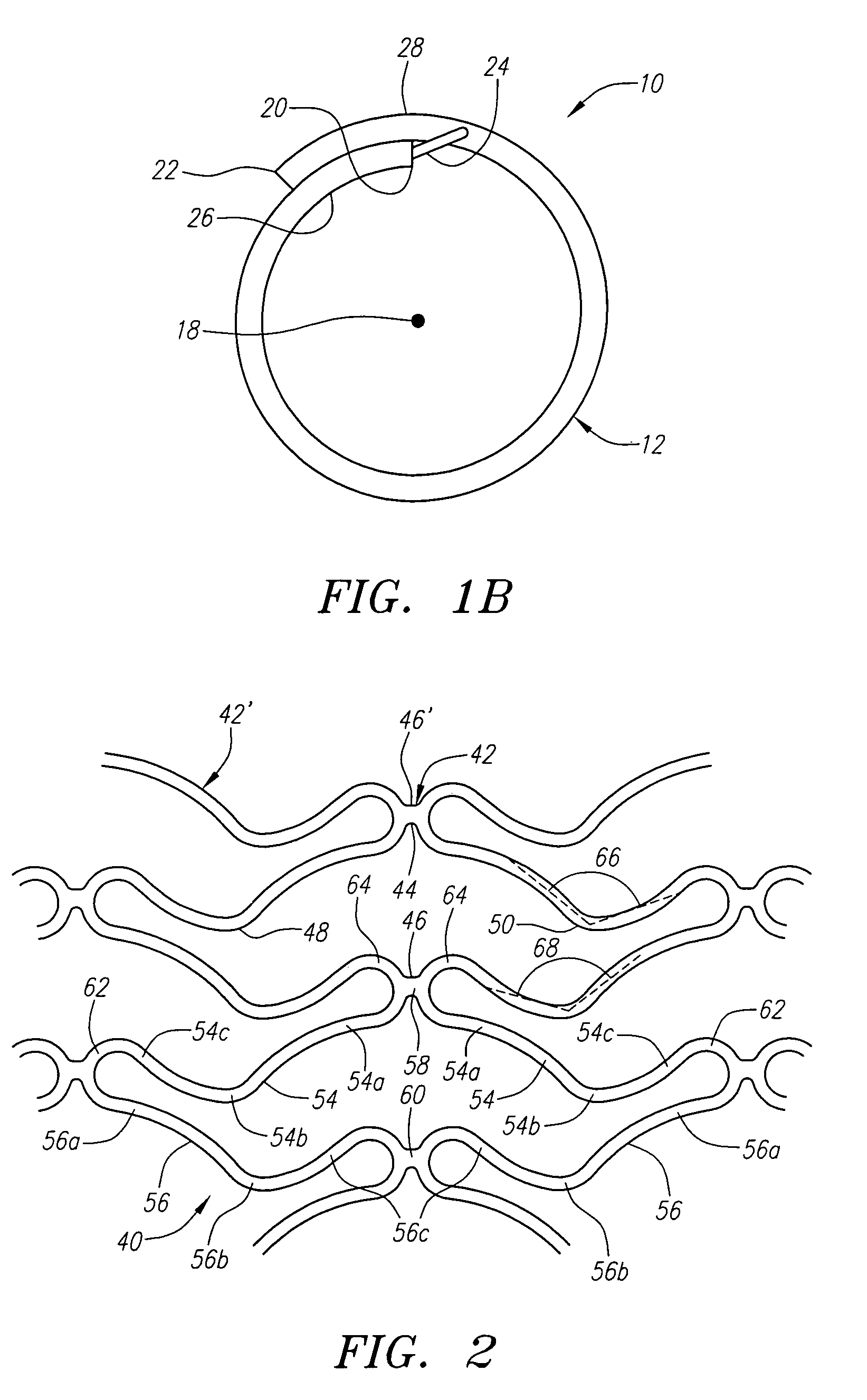
[0010]The diagonal elements have a generally arcuate shape, all diagonal elements in each band being oriented in either a clockwise or counter-clockwise direction about the circumference for facilitating packing of the diagonal elements in each band with one another. In a preferred form, each diagonal element includes a first member and a second member, each of the first and second members having first and second ends, the second ends being connected together by an elbow, the first ends being connected to preceding and succeeding diagonal elements in the zig-zag pattern. Preferably, the first and second members each have a slight curvature, with the curvature of the first member being opposite to the curvature of the second member (e.g., concave vs. convex). In a particularly preferred form, the first members forming the diagonal elements are slightly longer than the second members. In another particularly preferred form, the elbows are all identical to one another, and each elbow has an approximately 90° orientation in the unexpanded state of the stent (as described below), and an approximately 130° orientation when the stent is in its expanded state (as described below).
[0024]An advantage provided by the coiled sheet stents described herein is an improved balance of longitudinal flexibility and radial rigidity. For example, the coiled sheet stents described herein preferably incorporate a continuous mesh pattern having no discontinuities or discontinuous sections. The continuous mesh pattern provides a greater amount of radial rigidity when the stent is in its expanded state relative to a non-continous mesh pattern. Whereas prior art continuous mesh designs have suffered from a lack of longitudinal flexibility, particularly upon bending, the continuous mesh designs described herein provide relatively less bottom-compression and top-tension than those stents due to the described mesh pattern.

Problems solved by technology

Plastically deformable stents, however, may not expand uniformly and may not provide a desired delivery profile because of the need for a balloon on the delivery device underlying the stent.
Such stents, however, may not provide as small a delivery profile as desired and may not anchor against the wall of a vessel as securely as desired, which may lead to migration of the stent within the vessel.
A coiled-sheet stent, however, may be more rigid transverse to its longitudinal axis than tubular stents (depending upon the respective cell structures of the stents), potentially resulting in a less flexible stent, which may not be implanted as effectively in tortuous anatomical conditions.
Further, because the lattice-like structure of coiled-sheet stents is substantially nondeformable, if the stent is subjected to radially compressive forces, e.g., when the vessel wall attempts to contract, the stent may tend to buckle rather than recoil from the stress.

Method used


Image

  • Coiled-sheet stent with flexible mesh design
  • Coiled-sheet stent with flexible mesh design
  • Coiled-sheet stent with flexible mesh design

Examples


Embodiment Construction

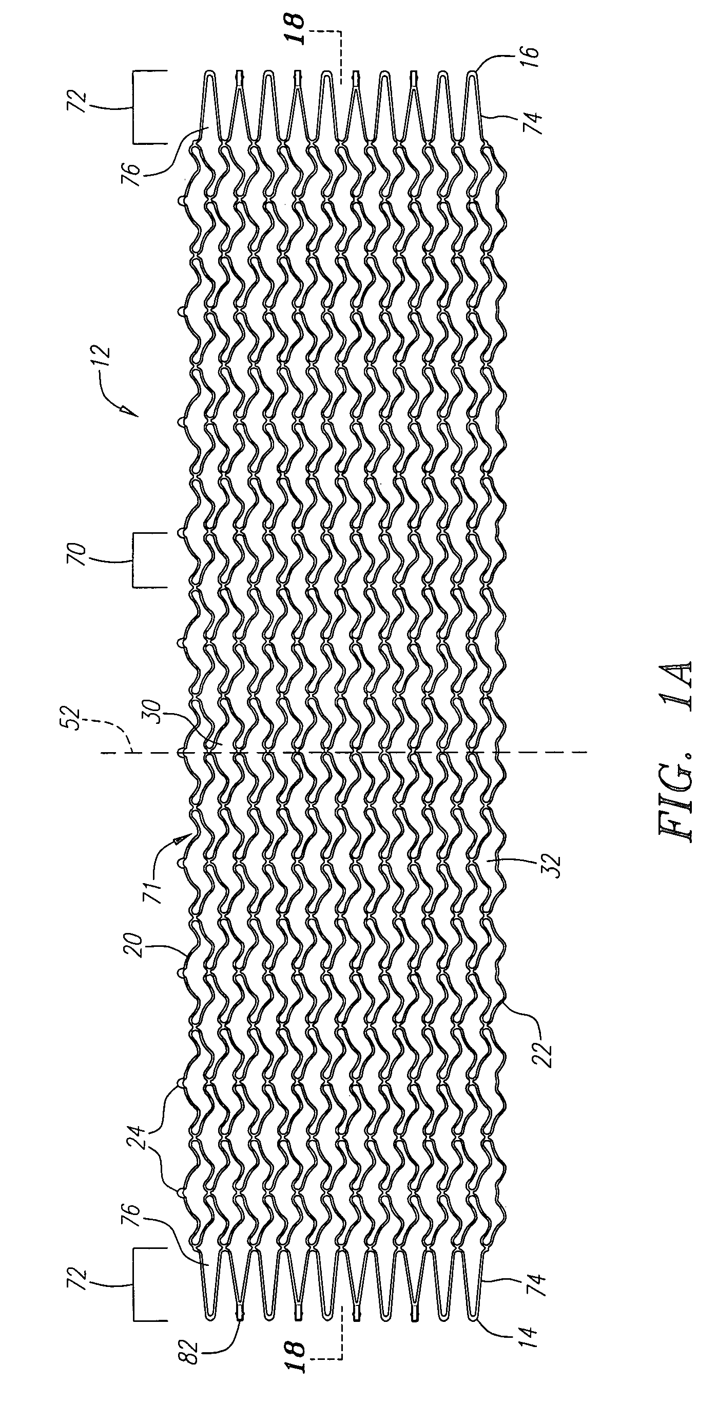
[0033]Turning now to the drawings, FIGS. 1A and 1B show a preferred embodiment of a coiled-sheet stent 10, in accordance with one aspect of the present invention. The coiled-sheet stent 10 is formed from a substantially flat sheet 12 having first and second ends 14, 16 defining a longitudinal axis 18 therebetween. The sheet 12 also includes first and second longitudinal edges 20, 22, the first edge 20 having a plurality of fingers or teeth 24 extending therefrom substantially perpendicular to the longitudinal axis 18.

[0034]The sheet 12 also includes a plurality of stretchable elements 30 formed therein, thereby defining a multi-cellular mesh structure capable of expanding and / or contracting in a direction substantially perpendicular to the longitudinal axis 18. Preferably, the stretchable elements 30 define a lattice-like structure providing a plurality of openings 32 for receiving the teeth 24, as described further below. Thus, each stretchable element generally defines an individu...


PUM


Abstract

A coiled-sheet stent includes a tubular body having a longitudinal axis and a circumference, and a plurality of cylindrical bands formed in the tubular body, each band having a zig-zag pattern including a series of sequential diagonal elements connected to one another and extending about the circumference. A plurality of longitudinal connectors extend between and connect adjacent bands. The diagonal elements have an arcuate shape, all diagonal elements in each band being oriented in either a clockwise or counter-clockwise direction about the circumference. The tubular body is expandable between contracted and enlarged conditions, and the zig-zag pattern is expandable between unstretched and unstretched conditions, the zig-zag pattern being biased towards the stretched condition above a transition temperature, thereby at least partially defining the enlarged condition. A multi-cellular stent structure is also provided that includes a plurality of bat shaped cells formed in a tubular body, each cell defining a head region, a tail region and opposing curved wing regions, and a plurality of connectors extending between and connecting adjacent cells. The head and tail regions of adjacent cells are directly connected to one another, and connectors extend between adjacent wing regions of adjacent cells.

Description

FIELD OF THE INVENTION[0001]The present invention relates generally to prostheses for implantation within body lumens, and more particularly to a coiled-sheet stent including a stretchable mesh design.BACKGROUND[0002]Tubular prostheses or “stents” are often implanted within blood vessels, for example, within the coronary and carotid arteries, for treating atherosclerotic disease which may involve one or more stenoses. Stents generally have a tubular shape capable of assuming a radially contracted condition to facilitate introduction into a patient's vasculature, and an enlarged condition for engaging the vessel wall at a treatment location. In its contracted condition, the stent may be placed on or in a delivery device, such as a catheter, percutaneously introduced into a patient's vasculature and advanced to a target treatment location. Once at the treatment location, the stent may be deployed and expanded to its enlarged condition, thereby engaging the wall of the vessel and subst...

Claims


Application Information

Patent Timeline
Patent Type & Authority Patents(United States)
IPC IPC(8): A61F2/06A61F2/92
CPCA61F2/91A61F2/915A61F2/92A61F2002/91525A61F2002/91541A61F2002/91558A61F2220/0008A61F2220/0016A61F2230/0054
Inventor YANG, YI
Owner ENDOTEX INTERVENTIONAL SYST
Learn More