Digital processing radar system

a radar system and digital processing technology, applied in the field of radar systems, can solve the problems of many vacuum tubes of radar systems giving rise to frequent failures, tube failures, reliability problems, etc., and achieve the effect of reducing aliasing in the downconversion

Inactive Publication Date: 2009-02-17
LOCKHEED MARTIN CORP
View PDF31 Cites 40 Cited by
  • Summary
  • Abstract
  • Description
  • Claims
  • Application Information

AI Technical Summary

Benefits of technology

[0011]In a particularly advantageous arrangement of this radar system. Each of the COTS MMIC transceivers further comprises bandpass filter means coupled to the input ports of the transmit I and Q modulators for filtering the analog I and Q modulation signals applied to the transmit I and Q modulators. In another advantageous arrangement, each of the transceivers further comprises bandpass filter means coupled to the output ports of the receive I and Q modulators for reducing aliasing in the downconverted I and Q receive signals. In a particularly advantageous version, each of the transceivers conforms to at least one of single-band IEEE 802-11 and IEEE 802.11a / g WLAN standards, which latter may be at 2.4 to 2.5 GHz and 4.9 to 5.87 GHz.

Problems solved by technology

Early radar systems used vacuum tubes in analog circuits, and were subject to reliability problems.
When left in operation, the many vacuum tubes of a radar system would give rise to frequent failures attributable to normal aging and often excessive heat.
If turned off when not in use, the thermal cycling would often result in tube failures at each turn-on, requiring trouble-shooting and maintenance.
Solid-state devices have been limited, however, in their ability to handle the large amounts of power required for radar transmissions.
The design of radar systems involves a complex tradeoff among many factors, among which are system complexity, cost, weight, performance, and reliability.
The problems associated with radar system design are more numerous and complex than might be thought.
Among other problems associated with radar system design are that the beamformers, circulators (if any), T / R modules, and filters (if any) associated with each elemental antenna of the antenna array tend to be physically large.
The large size of the T / R modules tends to make selection of an appropriate inter-antenna-element spacing difficult.
These analog modulation devices and analog beamformers are expensive, require considerable space, and must be cooled.

Method used


Image

  • Digital processing radar system
  • Digital processing radar system
  • Digital processing radar system

Examples


Embodiment Construction

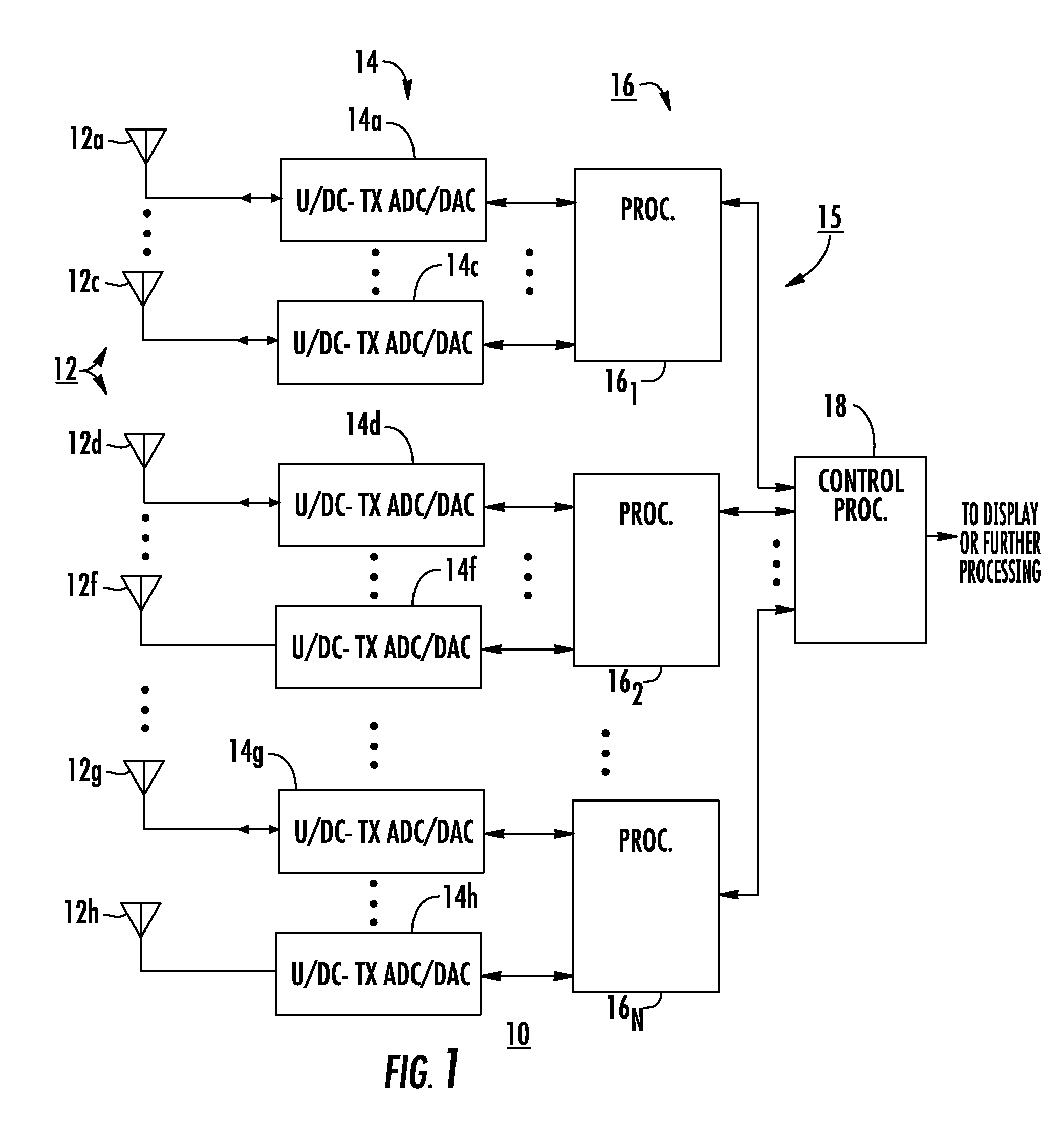
[0020]FIG. 1 is a simplified block diagram of a radar system 10 according to an aspect of the invention. In FIG. 1, a set 12 of antenna elements includes plurality of elemental antennas 12a . . . 12c, 12d . . . 12f, 12g . . . 12h arranged in an antenna array. Each of antenna elements 12a . . . 12c, 12d . . . 12f, 12g . . . 12h is connected by an analog signal path to an associated one of a set 14 of up / downconverter-transceiver ADC / DACs (U / DC-Tx ADC / DACs) 14a, . . . , 14c, 14d . . . , 14f, 14g . . . , 14h. Each (U / DC-Tx ADC / DAC) of set 14 is in analog communication with the associated elemental antenna of set 12 of antennas, and in digital communication with an associated digital processor. As illustrated in FIG. 1, U / DC-Tx ADC / DACs 14a, . . . , 14c communicate with a processor 161 of a set 16 of digital processors, U / DC-Tx ADC / DACs 14d, . . . , 14f communicate digitally with a processor 162, and U / DC-Tx ADC / DACs 14g, . . . , 14h communicate digitally with a processor 16N. Each of t...


PUM


Abstract

A radar system array antenna includes plural elements. Each element is coupled to a port of a transmit-receive device. Digital data representing the characteristics of the radar signal is applied to a monolithic IC combination DAC/ADC, which converts the digital data into analog transmit signal. The analog transmit signal is applied to a monolithic microwave IC transceiver, which may be monolithic with the DAC/ADC. The transceiver upconverts the transmit signal. The upconverted transmit signal is applied to a transmit port of the transmit-receive device and transmitted. Receive RF signal is coupled from each antenna element through the transmit-receive device to a receive signal port of the transceiver. The transceiver downconverts the receive signal to produce received downconverted signal. The downconverted signal is coupled to the ADC part of the DAC/ADC, which converts to receive digital signal. Digital processing processes the receive digital signal to produce the return target information.

Description

FIELD OF THE INVENTION[0001]This invention relates to radar systems, and more particularly to radar systems in which digital processing is coupled by a transceiver to each element of an array antenna.BACKGROUND OF THE INVENTION[0002]Radar systems are widely known. Early radar systems used vacuum tubes in analog circuits, and were subject to reliability problems. In particular, the vacuum tubes would age with time, and the operating parameters of the radar system would vary on an almost continuous basis, requiring constant realignment. When left in operation, the many vacuum tubes of a radar system would give rise to frequent failures attributable to normal aging and often excessive heat. If turned off when not in use, the thermal cycling would often result in tube failures at each turn-on, requiring trouble-shooting and maintenance.[0003]With the advent of solid-state devices, some of the low-frequency, low-power functions of a radar system could be converted away from tubes. This o...

Claims


Application Information

Patent Timeline
Patent Type & Authority Patents(United States)
IPC IPC(8): G01S7/28
CPCG01S7/032G01S7/28G01S2013/0254
Inventor EHRET, TIMOTHYMCGROARY, FRANCIS XAVIER
Owner LOCKHEED MARTIN CORP
Why Eureka
Try Eureka