Control circuit of power converter having adaptive bias for detecting reflected voltage of transformer

a technology of adaptive bias and control circuit, which is applied in the direction of dc-dc conversion, power conversion systems, inductances, etc., can solve the problem that the reflected voltage cannot be accurately measured, and achieve the effect of facilitating the detection of reflected voltage and preventing waveform distortion

Active Publication Date: 2009-02-17
SEMICON COMPONENTS IND LLC
View PDF5 Cites 13 Cited by
  • Summary
  • Abstract
  • Description
  • Claims
  • Application Information

AI Technical Summary

Benefits of technology

[0007]A control circuit is developed for detecting the reflected voltage of a transformer and regulating the power converter. It includes a switch and a controller, in which the switch is coupled to switch the transformer and to transfer the energy from the primary side to the secondary side of the transformer. The controller includes a detection circuit, a switching circuit, and an adjust circuit. The detection circuit is coupled to the transformer for detecting the reflected voltage of the transformer and for generating a feedback signal in accordance with the reflected voltage. The switching circuit is used for generating a control signal to control the switch and to regulate the output of the power converter in response to the feedback signal. The feedback signal is further used by the adjust circuit for generating an adjust signal. The detection circuit includes a bias circuit to generate a bias signal coupled to the input of the detection circuit for helping the reflected voltage detection and for preventing the waveform distortion. The bias signal is produced proportionally to the adjust signal. Besides the switching circuit, a blanking circuit is used for generating a blanking signal in response to the control signal. The blanking signal ensures a minimum on time of the control signal once the control signal is switched on. The minimum on time of the control signal produces a minimum pulse width of the reflected voltage, which further facilitates the reflected voltage detection.

Problems solved by technology

However, the disadvantage of the aforementioned reference is that the reflected voltage cannot be accurately measured, particularly at the light load condition.

Method used


Image

  • Control circuit of power converter having adaptive bias for detecting reflected voltage of transformer
  • Control circuit of power converter having adaptive bias for detecting reflected voltage of transformer
  • Control circuit of power converter having adaptive bias for detecting reflected voltage of transformer

Examples


Embodiment Construction

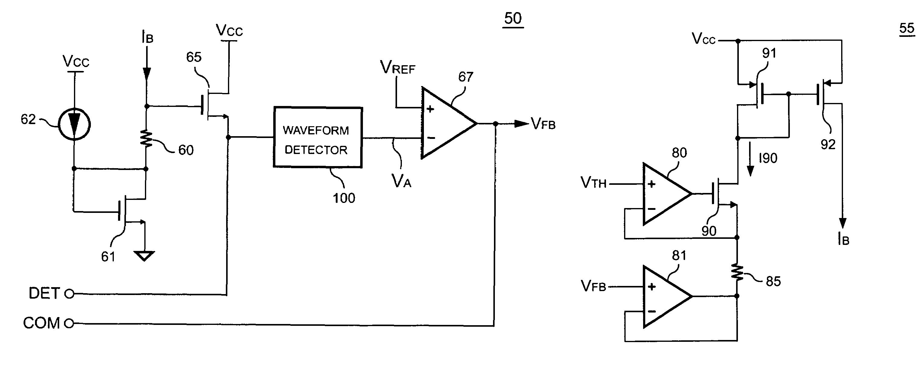
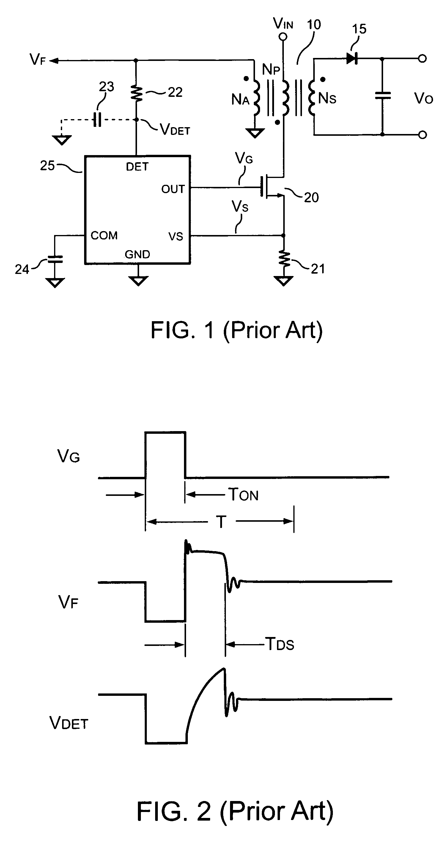
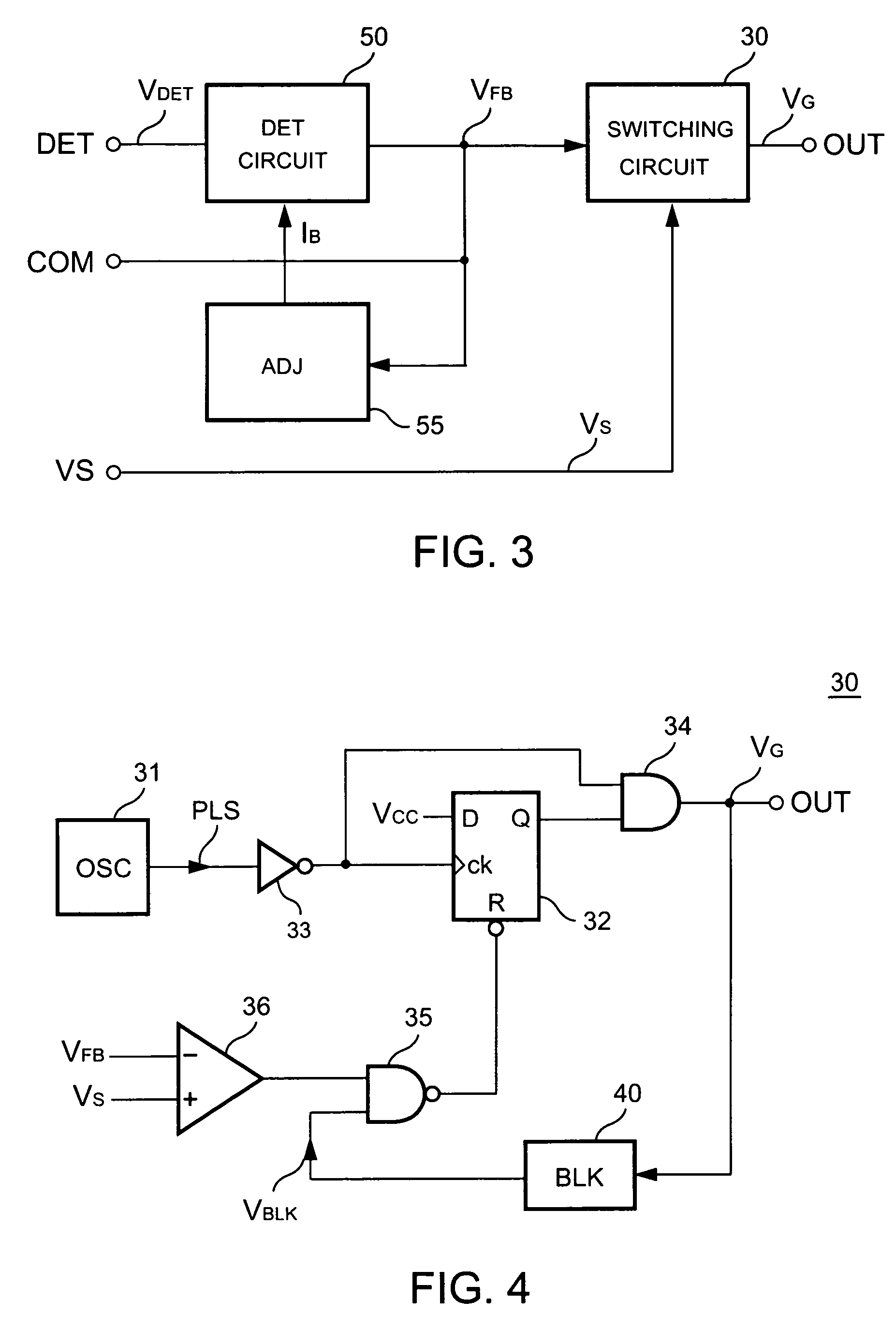
[0019]The control circuit of the power converter includes a switch 20 and a controller 25. The controller 25 generates a control signal VG to control the switch for switching the transformer 10. FIG. 3 shows a block schematic of the controller 25 according to the present invention. The controller 25 includes a switching circuit 30, a detection circuit 50, and an adjust circuit 55. Referring to FIG. 1, the detection circuit 50 is coupled to a transformer 10 for detecting the reflected voltage VF of the transformer 10 and generating a feedback signal VFB in accordance with the reflected voltage VF. The switching circuit 30 generates a control signal VG at the output terminal of the controller 25 for controlling the switch 20 and regulating the output of the power converter in response to the feedback signal VFB. The feedback signal VFB is further used by the adjust circuit 55 for generating an adjust signal IB.

[0020]The switching circuit 30 is shown in FIG. 4, in which an oscillation...


PUM


Abstract

A control circuit for detecting the reflected voltage of a transformer is provided. A detection circuit is developed for sampling the reflected voltage. Because the pulse width of the reflected voltage is narrower at light load, a bias circuit is utilized for producing a bias signal to help the reflected voltage detection. Furthermore, a blanking circuit ensures a minimum pulse width of the reflected voltage.

Description

BACKGROUND OF THE INVENTION[0001]1. Field of the Invention[0002]The present invention relates to a power converter, and more specifically relates to a switching power converter.[0003]2. Description of Related Art[0004]Power converters have been widely used for providing regulated outputs. For safety, the power converter must provide galvanic isolation between its primary side and secondary side. A transformer is usually equipped for providing the isolation and energy transfer. FIG. 1 shows a traditional power converter having a transformer 10. The energy is stored inside the transformer 10 when a switch 20 is turned on. The energy shall be discharged to the output of the power converter when the switch 20 is turned off. A resistor 21 is connected in series with the switch 20 for sensing the switching current of the transformer 10 and for generating a current signal VS for the switching control. A controller 25 is coupled to the transformer 10 and the resistor 21 for generating a con...

Claims


Application Information

Patent Timeline
Patent Type & Authority Patents(United States)
IPC IPC(8): H02M3/335
CPCH02M3/33523H01F27/38
Inventor YANG, TA-YUNGLI, CHUH-CHINGTSAO, FENG CHENG
Owner SEMICON COMPONENTS IND LLC
Why Eureka
Try Eureka