Call control system and method for automatic routing of circuit switched data connections based upon stored communication link information

a call control system and communication link technology, applied in the field of call control system and method for automatic routing of circuit switched data connections based upon stored communication link information, can solve the problems of mmp sessions being expensive in terms of router resources, unable to support mmp, and losing the cost advantage of a large system if many small rac blocks are scaled in order to achieve a larger system

Inactive Publication Date: 2009-02-17
CISCO TECH INC
View PDF8 Cites 4 Cited by
  • Summary
  • Abstract
  • Description
  • Claims
  • Application Information

AI Technical Summary

Benefits of technology

[0019]An embodiment of a call control system for routing multi-link connections, according to the present invention, is composed of a communications network including first and second switches. The first switch is configured to support a multi-link connection with an originating client and requests a connection by sending a connection set-up message into the communications network in response to a request from the originating client for each link of the multi-link connection. The connection set-up message identifies the originating client and a terminating client. A server is coupled to the second switch of the communications network and is configured to support a multi-link connection with the terminating client. The server has multiple communication devices where each communication device is coupled to the second switch through a corresponding transmiss

Problems solved by technology

MMP sessions can be expensive in terms of router resources and support for MMP can present a serious problem when scaled to large NAS systems having a large number of RACs.
The MMP support problem, in some cases, drives network design to use a single large central RAC for each NAS system.
However, the cost advantages to being able to scale many small RAC blocks in order to obtain a larger sys

Method used


Image

  • Call control system and method for automatic routing of circuit switched data connections based upon stored communication link information
  • Call control system and method for automatic routing of circuit switched data connections based upon stored communication link information
  • Call control system and method for automatic routing of circuit switched data connections based upon stored communication link information

Examples


Embodiment Construction

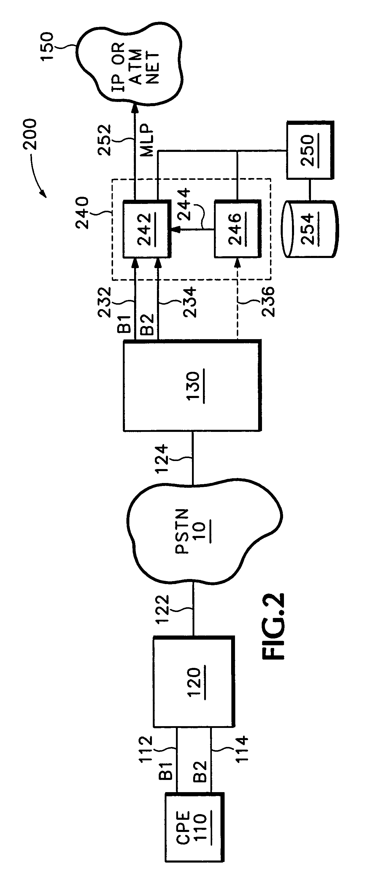
[0028]Referring now to FIG. 2, an embodiment of a network access server 240 according to the present invention is shown in an architecture 200. CPE 110 is connected to switch 120 which is connected to PSTN 10 through trunk facility 122. Network 150 is served by NAS 240 which consists of multiple RACs 242 and 246 which communicate via intra-chassis communication link 244. NAS 240 is connected to switch 130 of the PSTN 10 via multiple T1 facilities 232, 234 and 236. NAS 240 is also connected to routing processor 250 which maintains database 254.

[0029]Routing processor 250 monitors connections from clients served by NAS 240 and detects multi-link connections for clients served by NAS 240. However, the information which identifies a connection as part of a multi-link connection is typically not available until after a connection has been completed. For instance, it is typically not clear to NAS 240 that a multi-link connection is being established between CPE 110 and network 150 until a...


PUM


Abstract

A method and apparatus for automatic routing of multi-link circuit switched connections are shown. A routing processor monitors the behavioral characteristics of a previous connection from an originating client and stores data relating to the characteristics of the previous connection. In particular, data is stored regarding the previous connection which is not available until after call completion of the previous connection. When the originating client initiates a subsequent connection, the routing processor retrieves the data relating to the behavioral characteristics of the previous connection and efficiently routes the subsequent based upon the behavioral characteristics.

Description

[0001]This application claims priority and is a continuation of prior application Ser. No. 10 / 096,475, filed Mar. 12, 2002, now U.S. Pat. No. 6,643,703, titled, “Method and Apparatus for Automatic Routing of Circuit Switched Data Connections Based Upon Stored Behavioral Information” issued on Nov. 4, 2003, that claims priority and is a divisional of prior application Ser. No. 09 / 848,862, filed May 3, 2001, now U.S. Pat. No. 6,529,959, titled, “Method and Apparatus for Automatic Routing of Circuit Switched Data Connections Based Upon Stored Behavioral Information” issued on Mar. 4, 2003, that claims priority and is a continuation of prior application Ser. No. 09 / 225,897 filed Jan. 4, 1999, now U.S. Pat. No. 6,260,071, titled, “Method and Apparatus for Automatic Routing of Circuit Switched Data Connections Based Upon Stored Behavioral Information,” issued Jul. 10, 2001.BACKGROUND OF THE INVENTION[0002]A network access server (NAS) box typically provides dial-up internet services to us...

Claims


Application Information

Patent Timeline
IPC IPC(8): G06F13/00H04L12/56H04Q11/04
CPCH04Q11/0478H04L2012/563
Inventor ARMISTEAD, R. ASHBYSARGENT, ROBERT L.HAYS, TOD W.
Owner CISCO TECH INC
Why Eureka
Try Eureka