Heat sink with heat pipes

a heat sink and heat pipe technology, applied in the field of heat sinks, can solve the problems of failure to form a temperature gradient between one portion of the base and another portion of the base, the heat produced by the cpu in the computer, and the degradation of reliability and system malfunction, so as to enhance the heat-transfer performance of the heat pipe embedded in the base. the effect of maximizing the temperature gradien

Active Publication Date: 2009-02-24
CHAMP TECH OPTICAL FOSHAN
View PDF17 Cites 27 Cited by
  • Summary
  • Abstract
  • Description
  • Claims
  • Application Information

AI Technical Summary

Benefits of technology

[0004]Accordingly, what is needed is a heat sink which maximizes a temperature gradient on a base of the heat sink to thereby enhance heat-transfer performance of heat pipes embedded in the heat sink.
[0005]A heat sink in accordance with a preferred embodiment of the present invention comprises a base and heat pipes disposed in the base. The base comprises a bottom surface contacting with a heat-generating electronic component, an upper surface opposite the bottom surface, and grooves defined in the upper surface of the base receiving the heat pipes therein. The heat sink further comprises a fan. Each heat pipe comprises an evaporating section and a condensing section, wherein the evaporating sections of the heat pipes are located near a first end portion of the base, and the condensing portions are located near a second end portion of the base opposite the first end portion. A first fin assembly is mounted on the upper surface of the base, and a second fin assembly is mounted on the bottom surface of the base located near the second end portion of the base and corresponding to the condensing sections of the heat pipes, to thereby enhance heat dissipation of the condensing sections of the heat pipes to ambient air and maximize a temperature gradient on the base of the heat sink, so that heat absorbed by the base from the heat-generating component can be quickly spread to the second end portion of base. The fan is mounted adjacent to the second end portion of the base.

Problems solved by technology

This leads to a great deal of heat produced by the CPU in the computer.
If not been removed in time, the heat can accumulate on and overheat the CPU, resulting in degradation of reliability and system malfunction.
However, the heat from the heat-generating electronic component is evenly distributed on the base via the heat pipes, so the base fails to form a temperature gradient between one portion of the base and another portion of the base.
Heat transferred efficiency of the heat pipes is poor.

Method used


Image

  • Heat sink with heat pipes
  • Heat sink with heat pipes
  • Heat sink with heat pipes

Examples


Embodiment Construction

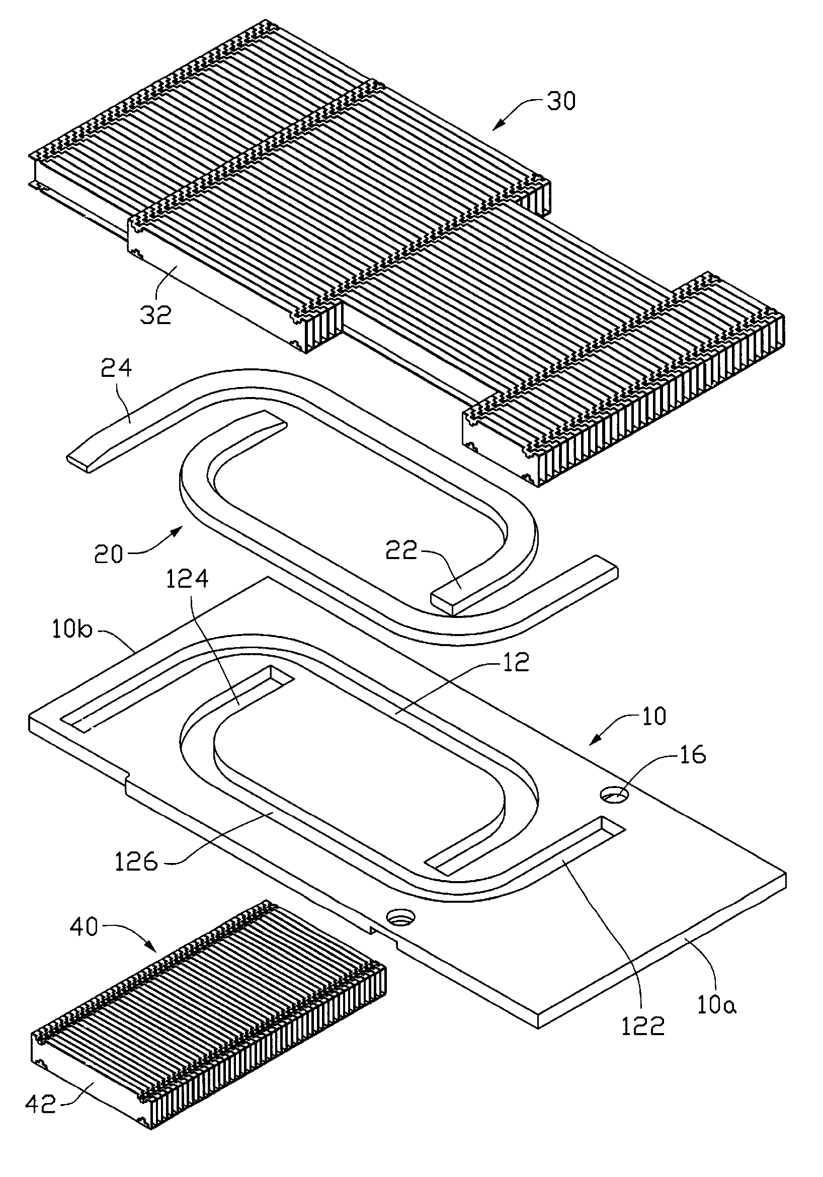
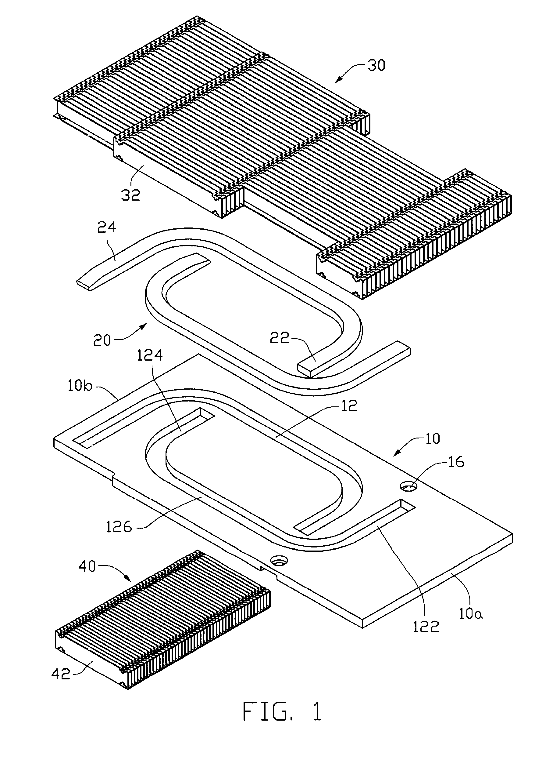
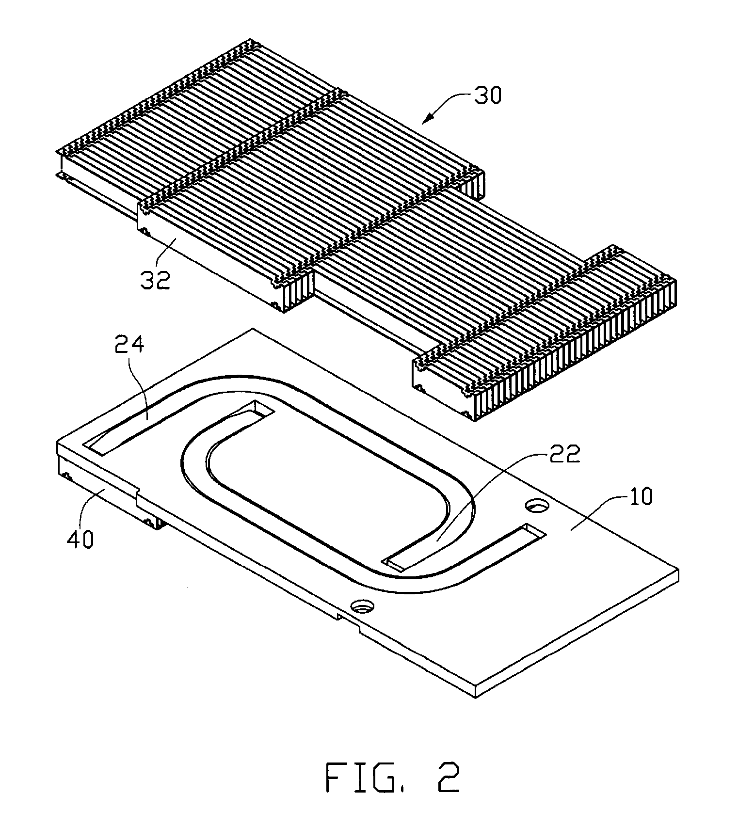
[0011]Referring to FIGS. 1-4, a heat sink in accordance with a preferred embodiment of the present invention comprises a base 10, two heat pipes 20 arranged on the base 10, a first fin assembly 30 and a second fin assembly 40 respectively disposed on upper and bottom surfaces of the base 10.

[0012]The base 10 is rectangular, and comprises a pair of long sides and a pair of short sides. The base 10 comprises a first end portion 10a and a second end portion 10b opposite the first end portion 10a. The first and second end portions 10a, 10b are coincident with the short sides of the base 10. A pair of grooves 12 is defined in the upper surface of the base 10 to receive the heat pipes 20 therein. The heat pipes 20 are flattened. The grooves 12 are U-shaped and extend from a portion of the base 10 near the first end portion 10a to a portion thereof near the second end portion 10b. Each groove 12 comprises a first depressed portion 122 located near the first end portion 10a of the base 10. ...


PUM


Abstract

A heat sink includes a base (10) and heat pipes (20). The base includes a bottom surface contacting with a heat-generating electronic component (100), an upper surface defining grooves (12) receiving the heat pipes therein. Evaporating sections (22) of the heat pipes are located near a first end portion (10a) and condensing sections (24) of the heat pipes are located near a second end portion (10b) of the base. A first fin assembly (30) is mounted on the upper surface and a second fin assembly (40) is mounted on the bottom surface of the base near the second end portion thereof. A fan (200) is located near the second end portion of the base.

Description

FIELD OF THE INVENTION[0001]The present invention relates to a heat sink for removing heat from a heat-generating electronic device, and more particularly to a heat sink having heat pipes embedded in the heat sink. The heat pipe extends from an end portion of the base to an opposite end portion of the base.DESCRIPTION OF RELATED ART[0002]Over the past few years, a CPU's operation speed has been increasing at a dramatic rate. In order to speedily process more information, the CPU must have more transistors, draw more power and have a higher clock rate. This leads to a great deal of heat produced by the CPU in the computer. If not been removed in time, the heat can accumulate on and overheat the CPU, resulting in degradation of reliability and system malfunction.[0003]Heat sink with heat pipes has been added to all modern CPUs to alleviate the effect of the heat on the processors by enforcing heat dissipation into the surrounding environment. A typical heat sink with heat pipes compri...

Claims


Application Information

Patent Timeline
Patent Type & Authority Patents(United States)
IPC IPC(8): F28D15/00H05K7/20
CPCH01L23/427H01L23/467F28D15/0275F28F1/32F28F3/02H01L2924/0002H01L2924/00
Inventor XIA, WAN-LINLI, TAOXIAO, MIN-QI
Owner CHAMP TECH OPTICAL FOSHAN
Why Eureka
Try Eureka