Solid-state magnet control

a magnet control and solid-state technology, applied in the field of magnet control, can solve the problems of high-magnitude voltage spike into the supply, damage and deterioration of equipment, and heat generation of magnets during use, so as to reduce maintenance requirements, inhibit circuit damage to the magnet control circuitry, and improve production efficiency

Active Publication Date: 2009-02-24
HUBBELL IND CONTROLS
View PDF35 Cites 16 Cited by
  • Summary
  • Abstract
  • Description
  • Claims
  • Application Information

AI Technical Summary

Benefits of technology

[0010]The present invention is a solid-state magnet control. The magnet control includes a housing and magnet control circuitry mounted within the housing. The magnet control circuitry includes an insulated gate bipolar transistor (IGBT) bridge configuration, and DUMP circuitry interconnected with the magnet control circuitry. The DUMP circuitry inhibits circuit damage to the magnet control circuitry and other components contained within the magnet control caused by overvoltage and / or voltage transients. The magnet control circuitry controls current passing through the magnet. The IGBT bridge configuration includes a LIFT HIGH IGBT, a LIFT LOW IGBT, a CLEAN HIGH IGBT, and a CLEAN LOW IGBT. The magnet control circuitry also includes a capacitor bank. The DUMP circuitry includes a DUMP HIGH IGBT, a discharge diode, and a discharge resistor.
[0011]The magnet control is configured to provide power loss ride through, ground fault detection, and discharge voltage control. The magnet control is also configured to accept increased voltage supply to reduce charge-up time of the magnet, and to accept existing operator control inputs through a relay interface.
[0013]The magnet control can be used in combination with a data terminal configured to determine status of a variety of parameters of the magnet control. The magnet control is configured to detect cut cables, to detect shorted cables, to control multiple magnets on a beam, and can include a battery backup to enable load to be maintained by a magnet upon loss of input voltage. The magnet control reduces maintenance requirements, improves production efficiency, and provides current control, as well as inhibits circuit damage to magnet control circuitry and other components contained within the magnet control caused by overvoltage and / or voltage transients.

Problems solved by technology

The problem with conventional magnet controllers is that the rapid change in magnet current (di / dt), caused when the load is switched across the magnet, induces a very high magnitude voltage spike into the supply.
These discharge voltage spikes can range from around 800 VDC to greater than around 1,500 VDC depending on the discharge load utilized and these voltage spikes can cause damage and deterioration of equipment.
Using traditional voltage control contactor based magnet controllers, magnets heat up during use due to internal electrical power losses proportional to the resistance of the magnet coil.
The rise in magnet temperature causes an increased resistance of the copper or aluminum magnet windings and, subsequently, causes proportionally greater internal power losses.
The reduced current acceptance reduces the capacity of the magnet, the magnet is able to pick up less material, and the reduced efficiency results in reduced production throughput.
Because traditional technology does not control magnet current, use of a higher voltage supply would induce magnet currents greater than the magnet can withstand.

Method used


Image

  • Solid-state magnet control
  • Solid-state magnet control
  • Solid-state magnet control

Examples


Embodiment Construction

[0022]The present invention is a solid-state magnet control. The invention disclosed herein is, of course, susceptible of embodiment in many different forms. Shown in the drawings and described herein below in detail are preferred embodiments of the invention. It is to be understood, however, that the present disclosure is an exemplification of the principles of the invention and does not limit the invention to the illustrated embodiments.

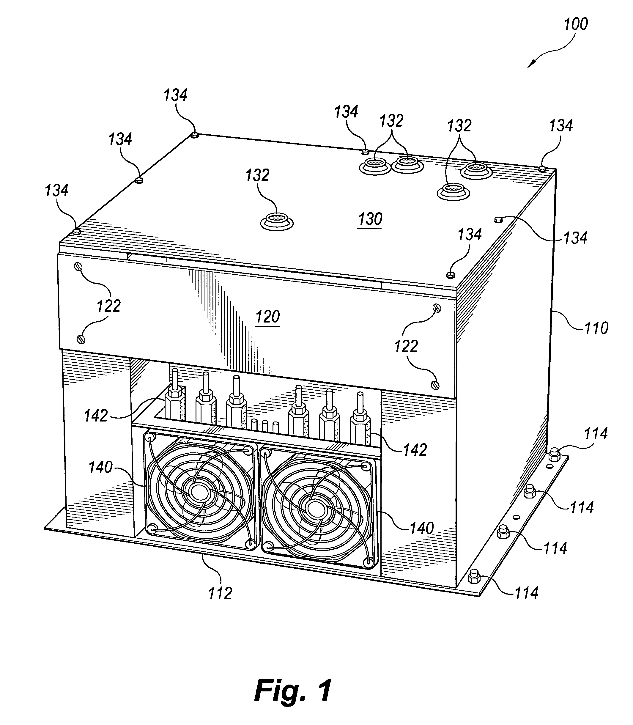
[0023]Referring to the drawings, FIG. 1 shows a solid-state magnet control 100 according to the invention. The magnet control 100 has a housing 110 with a base 112. The base can be fastened to a support by fasteners 114. The housing 110 includes a front panel 120 removably mounted by fasteners 122 and a tot panel removably mounted by fasteners 134. Fans 140 are mounted behind fan guards in the housing 110. Terminals 142 and additional elements are also mounted in the housing 110. Terminals 142 are for interconnecting the magnet control 100 to a mag...


PUM


Abstract

A solid-state magnet control includes a housing and magnet control circuitry mounted within the housing. The magnet control circuitry includes an insulated gate bipolar transistor (IGBT) bridge configuration and DUMP circuitry. The DUMP circuitry inhibits circuit damage to the magnet control circuitry and other components contained within the magnet control caused by overvoltage and / or voltage transients. The magnet control circuitry controls current passing through the magnet. The IGBT bridge configuration includes a LIFT HIGH IGBT, a LIFT LOW IGBT, a CLEAN HIGH IGBT, and a CLEAN LOW IGBT, as well as a capacitor bank. The DUMP circuitry includes a DUMP HIGH IGBT, a discharge diode, and a discharge resistor. The magnet control is configured to provide power loss ride through, ground fault detection, and discharge voltage control, and can accept increased voltage supply to reduce charge-up time of the magnet, and existing operator control inputs through a relay interface.

Description

BACKGROUND OF THE INVENTION[0001]1. Field of the Invention[0002]The present invention generally relates to magnet controls and, more particularly to a solid-state magnet control.[0003]2. Description of Related Art[0004]Electromagnets for use in lifting, crane, and / or any other similar operations are well known and are used for the positioning and handling of ferromagnetic materials including steel products or the like in a variety of arrangements including processing machines, pick-and-place units, automation projects, etc. Such electromagnets can be used in the lifting of flat, round, and / or other shapes of ferromagnetic materials. Operating modes for use with lifting magnets typically include LIFT, DROP, and / or DRIBBLE operating modes.[0005]Magnet controllers using existing technology typically require the input power supply voltage to be above a minimum level in order to maintain holding of the load and to provide control power voltage to their contactor coils. Upon loss of input...

Claims


Application Information

Patent Timeline
Patent Type & Authority Patents(United States)
IPC IPC(8): H01H47/00
CPCH01F7/18H01F7/206H02H9/047
Inventor THEXTON, ANDREW S.CHRISTENSON, ERIC S.
Owner HUBBELL IND CONTROLS
Why Eureka
Try Eureka