Transmitter apparatus and wireless communication apparatus

a transmitter and wireless communication technology, applied in the field of transmitter apparatus and wireless communication apparatus, can solve the problems of dc bias component power consumption, rapid change, efficiency degradation, etc., and achieve the effect of excellent distortion characteristic and high efficiency of polar coordinate modulation

Active Publication Date: 2009-02-24
REDWOOD TECHNOLOGIES LLC
View PDF9 Cites 26 Cited by
  • Summary
  • Abstract
  • Description
  • Claims
  • Application Information

AI Technical Summary

Benefits of technology

[0034]According to the invention, it is possible to provide a transmitter capable of carrying out a highly efficient polar coordinate modulation while maintaining an excellent distortion characteristic, and a radio communicating device.

Problems solved by technology

On the other hand, a power with a DC bias component is always consumed.
As a result, there is a problem in that the efficiency is deteriorated.
In the transmission wave generating method and apparatus according to the related example, however, an amplitude limitation is carried out only when an instantaneous value of an amplitude is greater than the amplitude limit value (a hard clipping operation) so that a rapid change is generated in the vicinity of the amplitude limit value.
As a result, there is a problem in that a nonlinear distortion is easily increased.

Method used


Image

  • Transmitter apparatus and wireless communication apparatus
  • Transmitter apparatus and wireless communication apparatus
  • Transmitter apparatus and wireless communication apparatus

Examples


first embodiment

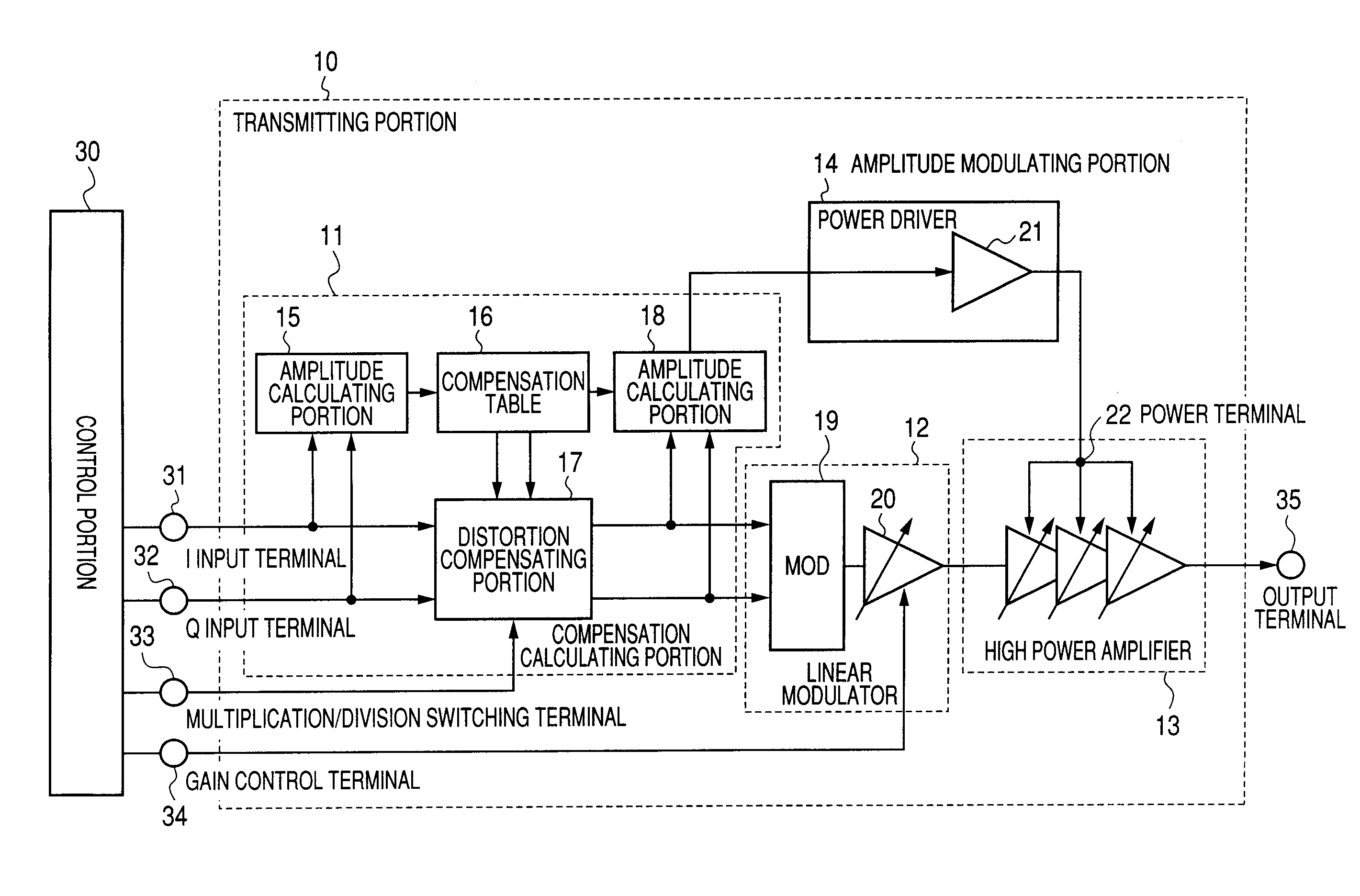
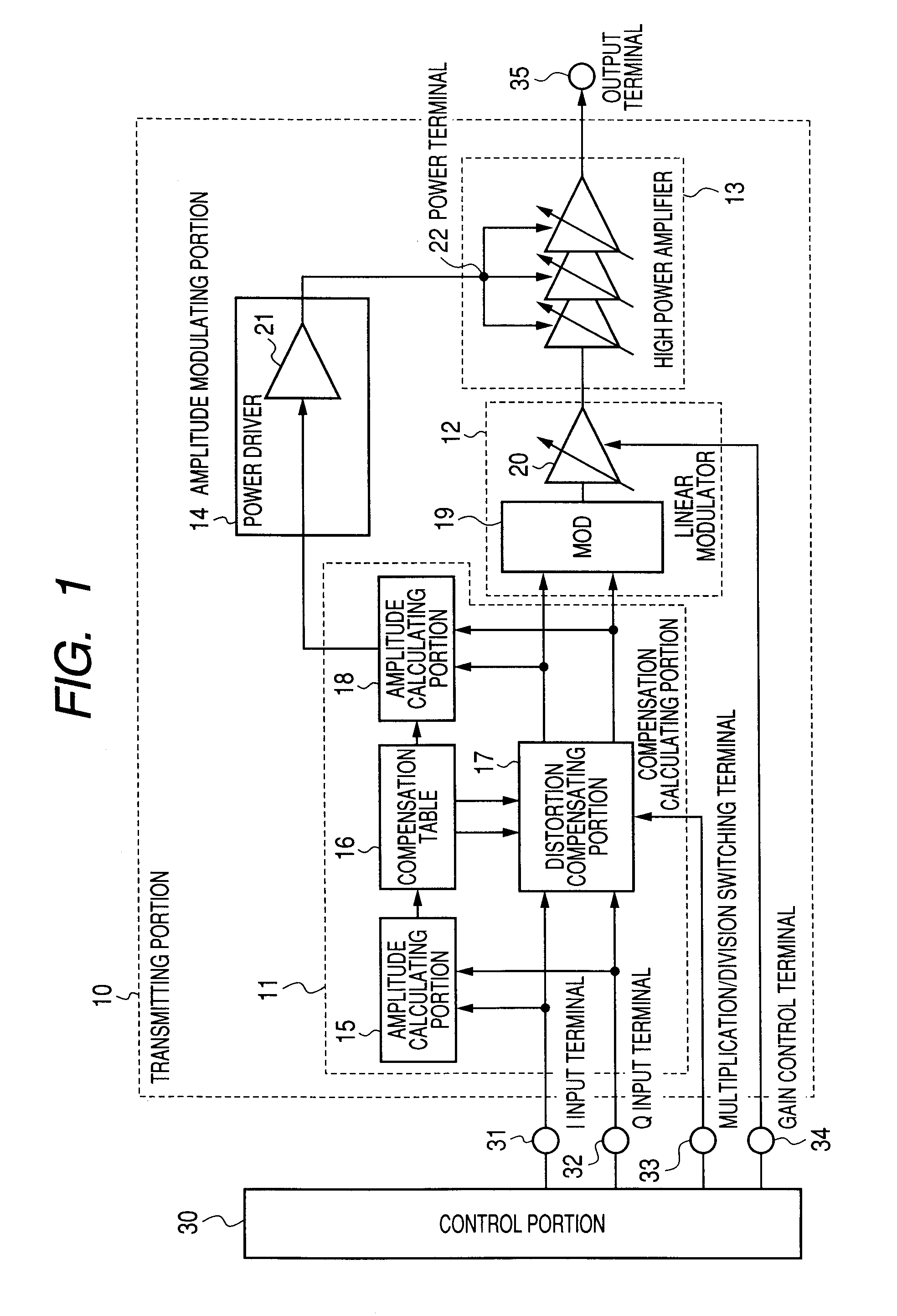
[0094]FIG. 1 is a block diagram showing a structure of a transmitter according to a first embodiment of the invention. A transmitting portion 10 constituting the transmitter according to the first embodiment is constituted to include a compensation calculating portion 11 for calculating a distortion compensation, a linear modulator 12, a high power amplifier 13 for amplifying a power of a transmitting signal output from the linear modulator 12, and an amplitude modulating portion 14 for generating a power to be supplied to the high power amplifier 13.

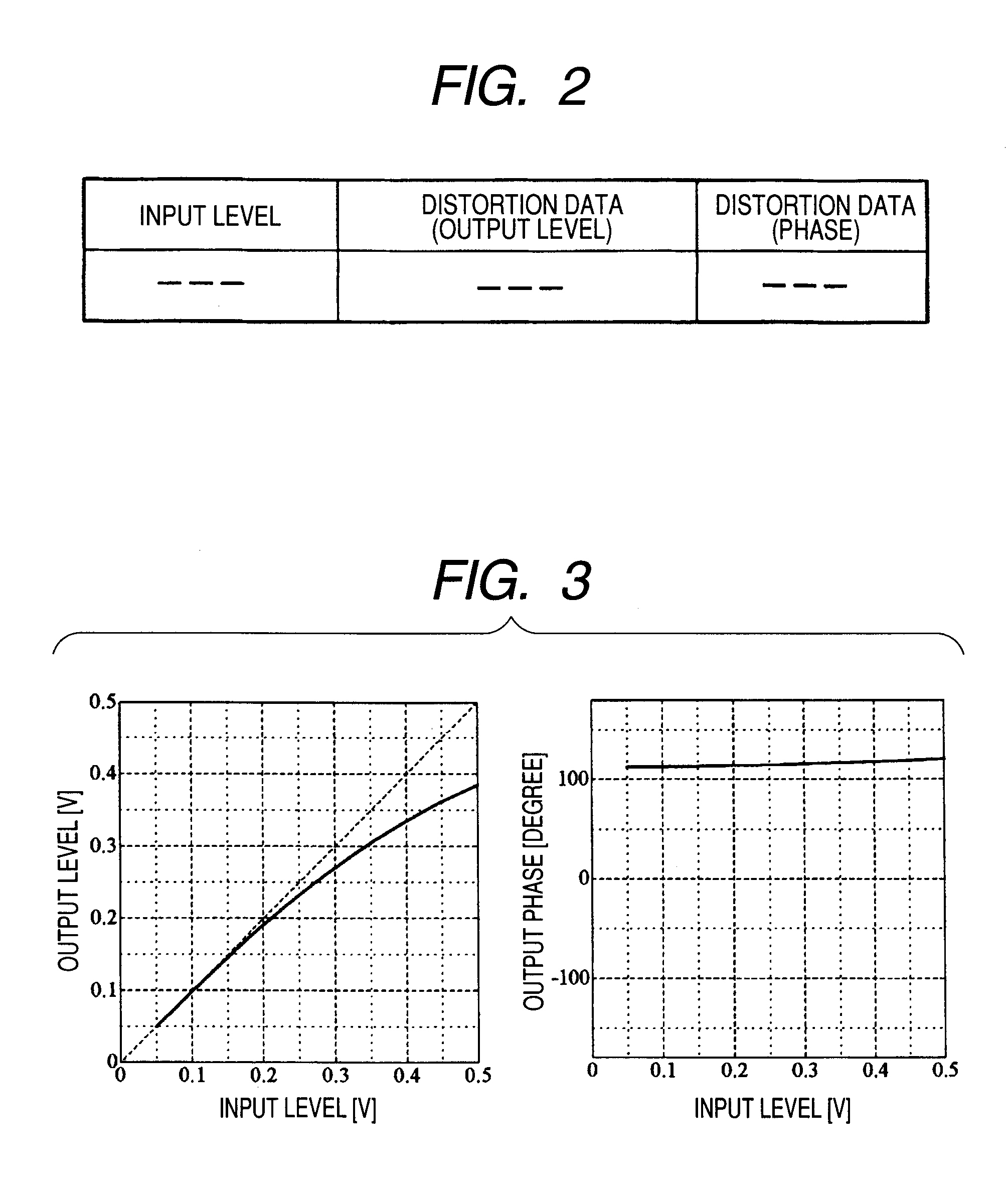
[0095]The compensation calculating portion 11 is constituted to have a first amplitude calculating portion 15 for calculating an amplitude of a baseband zone quadrature modulating digital signal, a compensation table 16 for storing distortion data on a normal characteristic or a reverse characteristic of an output level and a phase corresponding to each input level of the high power amplifier 13, a distortion compensating portion 17 for...

second embodiment

[0110]FIG. 4 is a block diagram showing a structure of a transmitter according to a second embodiment of the invention. A transmitting portion 40 according to the second embodiment is partially different from the structure according to the first embodiment and a structure of a compensation calculation portion 41 is changed.

[0111]The compensation calculating portion 41 includes a compensation table 42 in which distortion data on a normal characteristic and a reverse characteristic are stored as a plurality of distortion data in place of the compensation table 16 according to the first embodiment, and the compensation table 42 is provided with a normal / reverse characteristic switching terminal 43 for inputting a switching control signal. The distortion data to be output from the compensation table 42 are switched in response to the switching control signal input through the normal / reverse characteristic switching terminal 43 and a distortion compensation is carried out by only a multi...

third embodiment

[0117]FIG. 7 is a block diagram showing a structure of a transmitter according to a third embodiment of the invention. A transmitting portion 50 according to the third embodiment is partially different from the structure according to the first embodiment and a compensation calculating portion 51 for carrying out a distortion compensation in an amplitude component is provided.

[0118]The compensation calculating portion 51 is constituted to have an amplitude calculating portion 15 for calculating an amplitude of a baseband quadrature modulating digital signal, a distortion table 52 storing distortion data on an amplitude component, and a distortion adding portion 53 for adding the distortion data transferred from the distortion table 52 to the amplitude output from the amplitude calculating portion 15 and supplying them to an amplitude modulating portion 14. The other structures are the same as those in the first embodiment, and the same components have the same reference numerals and ...


PUM


Abstract

A transmitter capable of carrying out a highly efficient polar coordinate modulation while maintaining an excellent distortion characteristic. When a high power amplifier is operated in a saturation mode to carry out a polar coordinate modulation, a switching control signal is set to be a multiplication, and a quadrature modulating digital signal and distortion data of a compensation table are multiplied, thereby adding a nonlinear distortion equivalent to that of the amplifier in a linear mode and compressing a peak factor of a modulating signal to enhance an efficiency of the polar coordinate modulation. When the amplifier is operated in the linear mode to carry out a linear amplification, the switching control signal is set to be a division and the quadrature modulating digital signal and the distortion data are divided, thereby adding a reverse distortion characteristic of the amplifier to carry out a nonlinear distortion compensation of the amplifier.

Description

TECHNICAL FIELD[0001]The present invention relates to a transmitter capable of amplifying a transmission power using a polar coordinate modulation and a radio communicating device using the transmitter.BACKGROUND ART[0002]In a transmitter to be used in mobile telecommunications, a power efficiency and a linearity in a transmitting function are evaluated as an index for indicating a performance of the device. In particular, the power efficiency and the linearity in the transmitting function are the most important indices for representing the performance of the device in a high frequency modulation transmitting apparatus such as a cell phone.[0003]For an amplifier in a final stage of the high frequency modulation transmitting apparatus, an amplifier for carrying out a so-called AB class operation has widely been used. The AB class amplifier has a small distortion, that is, is excellent in the linearity. On the other hand, a power with a DC bias component is always consumed. For this r...

Claims


Application Information

Patent Timeline
Patent Type & Authority Patents(United States)
IPC IPC(8): H04B1/04H04L27/36H03C7/02H03F1/02H03F1/06H03F1/32H03F3/24H03G3/10
CPCH03F1/0205H03F1/0211H03F1/0261H03F1/32H03F1/3223H03F3/24H04L27/361H04L27/367H03F2200/331H04B1/0475
Inventor SAITO, NORIAKI
Owner REDWOOD TECHNOLOGIES LLC
Why Eureka
Try Eureka