Column-and-beam join structure

a join structure and column-and-beam technology, applied in the direction of girders, shock-proofing, manufacturing tools, etc., can solve the problems of inability to meet the requirements of construction, inconvenient, and ineffective energy absorption, so as to achieve the effect of the present invention

Inactive Publication Date: 2009-03-03
NIPPON STEEL CORP
View PDF20 Cites 49 Cited by
  • Summary
  • Abstract
  • Description
  • Claims
  • Application Information

AI Technical Summary

Benefits of technology

[0053]FIG. 18(a) shows the case where a split tee produced from a conventional steel material (SS material: JISG3101, etc.) is used. In this case, if the lower limit of the yield stress (σ min) of a steel material is defined to be the yield stress in design, as the upper limit of the yield stress (σ max) is not regulated, it sometimes happens that a steel material having a very high yield stress is used and a column tends to yield in advance. In the case where an SN material (JISG3106) is assumed to be used for a split tee as shown in FIG. 18(b), the upper limit of the yield stress of the material is 1.35 to 1.5 times the lower limit of the yield stress. In the case where a steel material developed by the present inventors i...

Problems solved by technology

However, since the flexural strength of the flanges of the split tees is critical in design, the thickness and width of the flanges must be increased in order to sufficiently secure the rigidity and proof stress of the flanges, and therefore it is not economical.
On the other hand, in the case of designing a final collapse system for a large earthquake or the like, it is not desirable to make the join portions of a steel column and split tees rupture, and therefore it is an original technique to design the system so as to impose all cross-sectional proof stress on a steel beam so that the rupture may occur in the steel beam itself.
Therefore, even though a system is designed so as to impose all cross-sectional proof stress on a beam, since there are cases where the proof stress of the beam is excessively large, the rupture may occur in bolts, split tees or the portion to which a column is connected, which have no allowance in proof stress, as a result.
However, in the case where the ...

Method used


Image

  • Column-and-beam join structure
  • Column-and-beam join structure
  • Column-and-beam join structure

Examples


Embodiment Construction

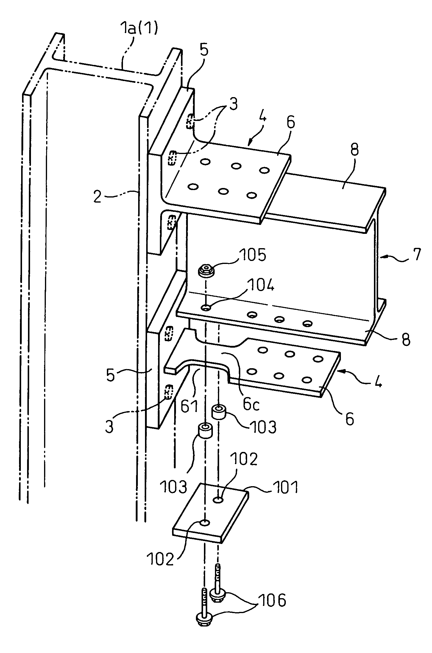
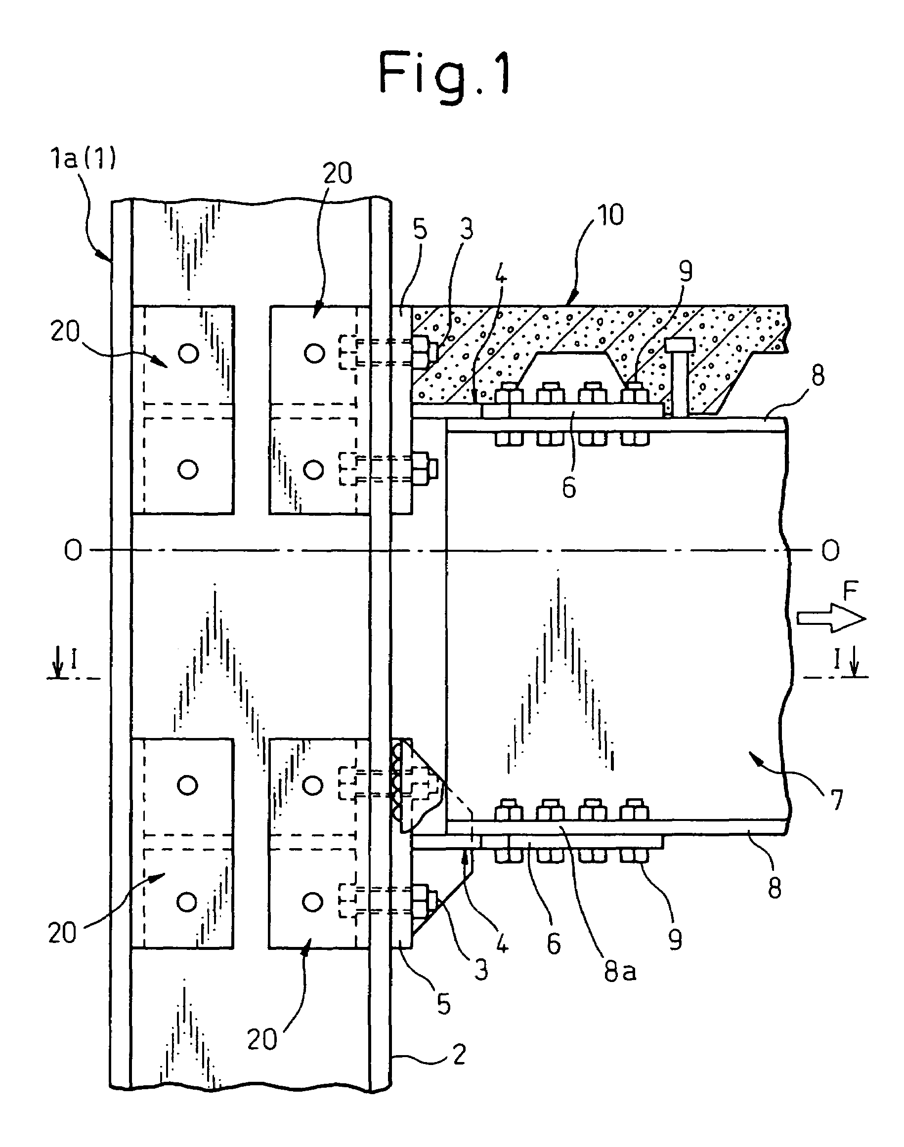
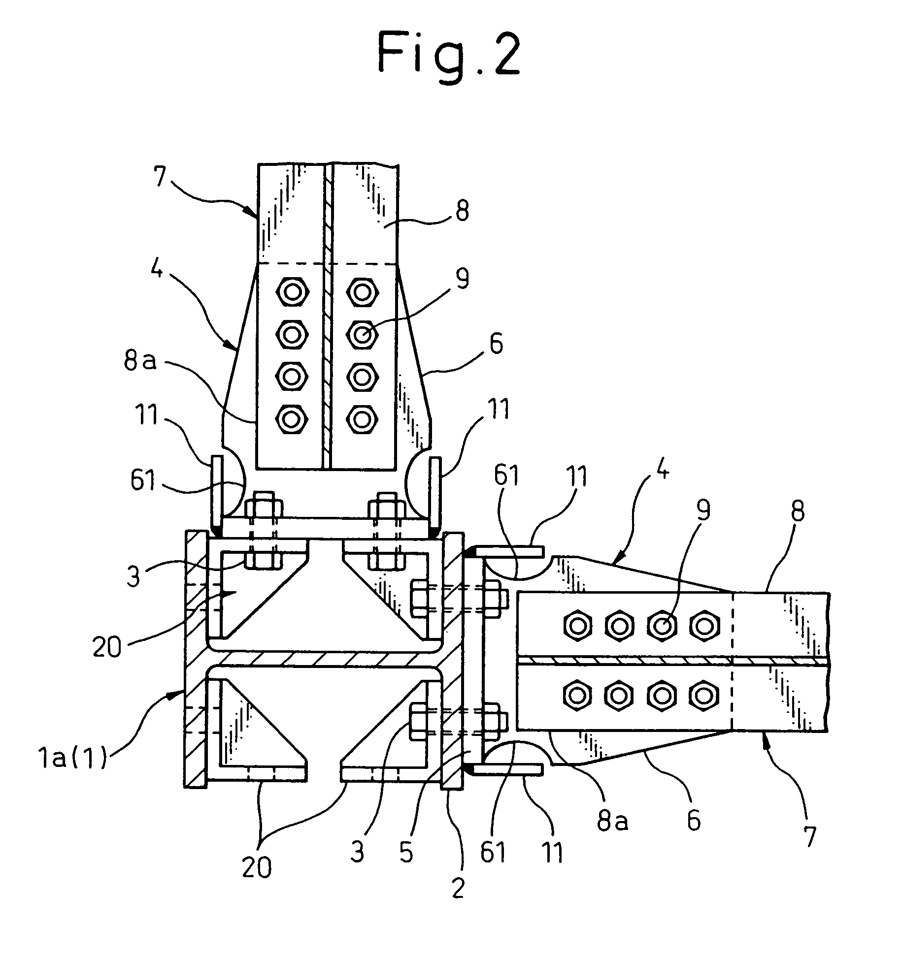
[0091]The embodiments of the present invention will be explained in detail, by referring to the drawings, hereunder. FIGS. 1 to 3 show the first embodiment of a column-and-beam join structure according to the present invention.

[0092]As shown in FIGS. 1 to 3, an H-shaped steel column 1a(1) is used as a steel column 1, the flanges 5 of a pair of upper and lower split tees 4 are connected to a flange 2 of the H-shaped steel column 1a(1) using bolts 3, and the end portions 8a of both upper and lower flanges 8 of an H-shaped steel beam 7 used as a steel beam are attached between the webs 6 of both the upper and lower split tees 4 and are connected to the webs 6 using bolts 9.

[0093]Then, a concrete slab 10 is molded on the upper flange 8 of the H-shaped steel beam 7 as a floor material, and, in this case, a conventional split tee is used as the upper split tee 4 which connects the upper flange 8 of the H-shaped steel beam 7 to a flange 2 of the H-shaped steel column 1a(1).

[0094]On the oth...


PUM


Abstract

A column-and-beam join structure comprises connecting the column and beam with a pair of split tees. At least one split tee has a web with a portion of the web having a reduced cross-sectional area. The web with the reduced cross-sectional area is located between a flange of the beam and a buckling restraint. The buckling restraint is connected to the flange of the beam with bolts. The sides of the bolts are in the proximity to the side surface of the portion of the web of the split tee having the reduced cross-sectional area. Annular members may be arranged surrounding portions of the bolts that are in proximity to the side surface of the portion of the web having the reduced cross-sectional area.

Description

[0001]This application is a continuation-in-part application under 35 U.S.C. §120 of prior application Ser. No. 10 / 163,475 filed Jun. 5, 2002 now U.S. Pat. No. 6,739,099.TECHNICAL FIELD[0002]The present invention relates to a column-and-beam join structure having a vibration-mitigating property in a steel frame when a steel structure building is constructed and, more specifically, to a column-and-beam join structure capable of absorbing the energy of an earthquake by split tees yielding before the column and the beam in a column-and-beam join structure which is made of a steel column and a steel beam using split tees.[0003]In a column-and-beam join structure according to the present invention, the steel column includes not only an H-shaped steel column or a square steel tube column but also a column of any cross-sectional shape which may be connected using split tees, and the steel beam includes not only an H-shaped steel beam but also a section beam of an L-shape, a T-shape, or ano...

Claims


Application Information

Patent Timeline
IPC IPC(8): E04B1/08E04B1/24E04B5/10E04C3/04E04C3/30
CPCE04B1/2403E04C3/04E04C3/30E04H9/024E04B5/10Y10T403/73E04B2001/2415E04B2001/2439E04B2001/2442E04B2001/2448E04B2001/2454E04C2003/0413E04C2003/0421E04C2003/043E04C2003/0434E04C2003/0452E04C2003/0465F16B2200/67
Inventor TAKEUCHI, TORUMAEDA, YASUSHISUZUKI, KAZUAKIOKADA, KENYAMADA, SATOSHIWADA, AKIRA
Owner NIPPON STEEL CORP
Why Eureka
Try Eureka