Medical ventilator with compressor heated exhalation filter

a ventilator and compressor technology, applied in the field of medical ventilators, can solve the problems of increasing the temperature of the pressurized gas provided to the patient, reducing the efficiency of the resistive heating element, and increasing the temperature of the bacteria filter at the expense, so as to achieve the effect of increasing the gas pressur

Inactive Publication Date: 2009-03-03
RIC INVESTMENTS LLC
View PDF12 Cites 37 Cited by
  • Summary
  • Abstract
  • Description
  • Claims
  • Application Information

AI Technical Summary

Benefits of technology

[0019]The invention is also a method of heat transfer in a medical ventilator. The method includes providing a pressure generator for increasing a pressure of gas to be delivered to a patient and providing a thermally conductive heat sink spaced from the pressure generator. Heat is produced in response to operation of the pressure generator and a thermal conductor is coupled in thermal communication between the pressure generator and the heat sink for transferring at least part of the heat produced by the pressure generator to the heat sink.
[0020]The method can also include coupling to the heat sink a component requiring heating in excess of an ambient temperature for the effective operation thereof whereupon the component receives heat from the thermal conductor via the heat sink.
[0021]Lastly, the invention is a medical ventilator that includes means for increasing a pressure of gas that produces heat during the operation thereof; means for absorbing heat spaced from the gas pressure increasing means; means requiring heating in excess of an ambient temperature for the effective operation thereof, with heat requiring means coupled in

Problems solved by technology

Because the pressure generator is utilized to increase the pressure of gas provided to a patient, the heat trapped in the pressure generator undesirably increases the temperature of the pressurized gas provided to the patient.
Moreover, the trapped heat increases the operating temperature of the press

Method used


Image

  • Medical ventilator with compressor heated exhalation filter
  • Medical ventilator with compressor heated exhalation filter
  • Medical ventilator with compressor heated exhalation filter

Examples


Embodiment Construction

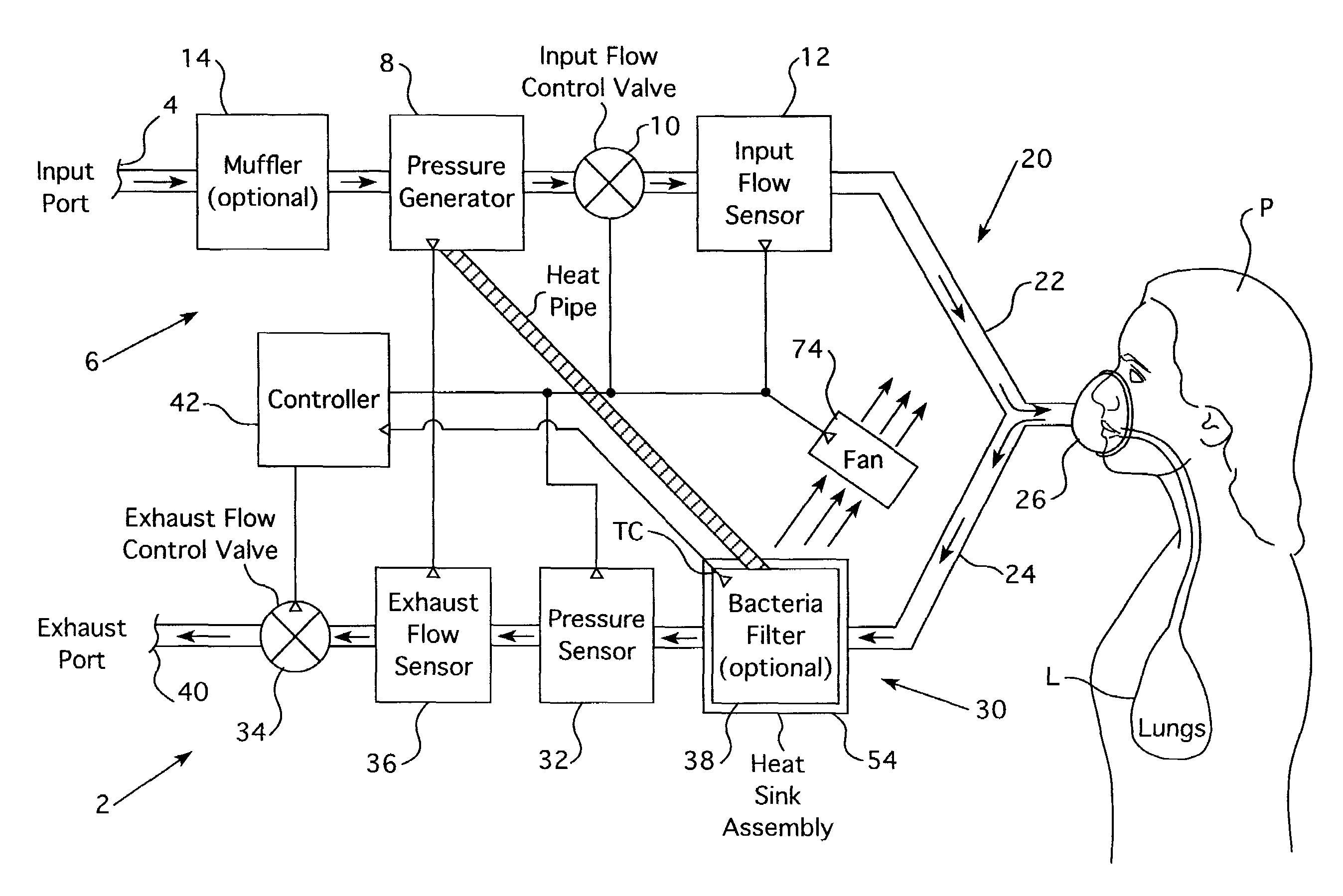
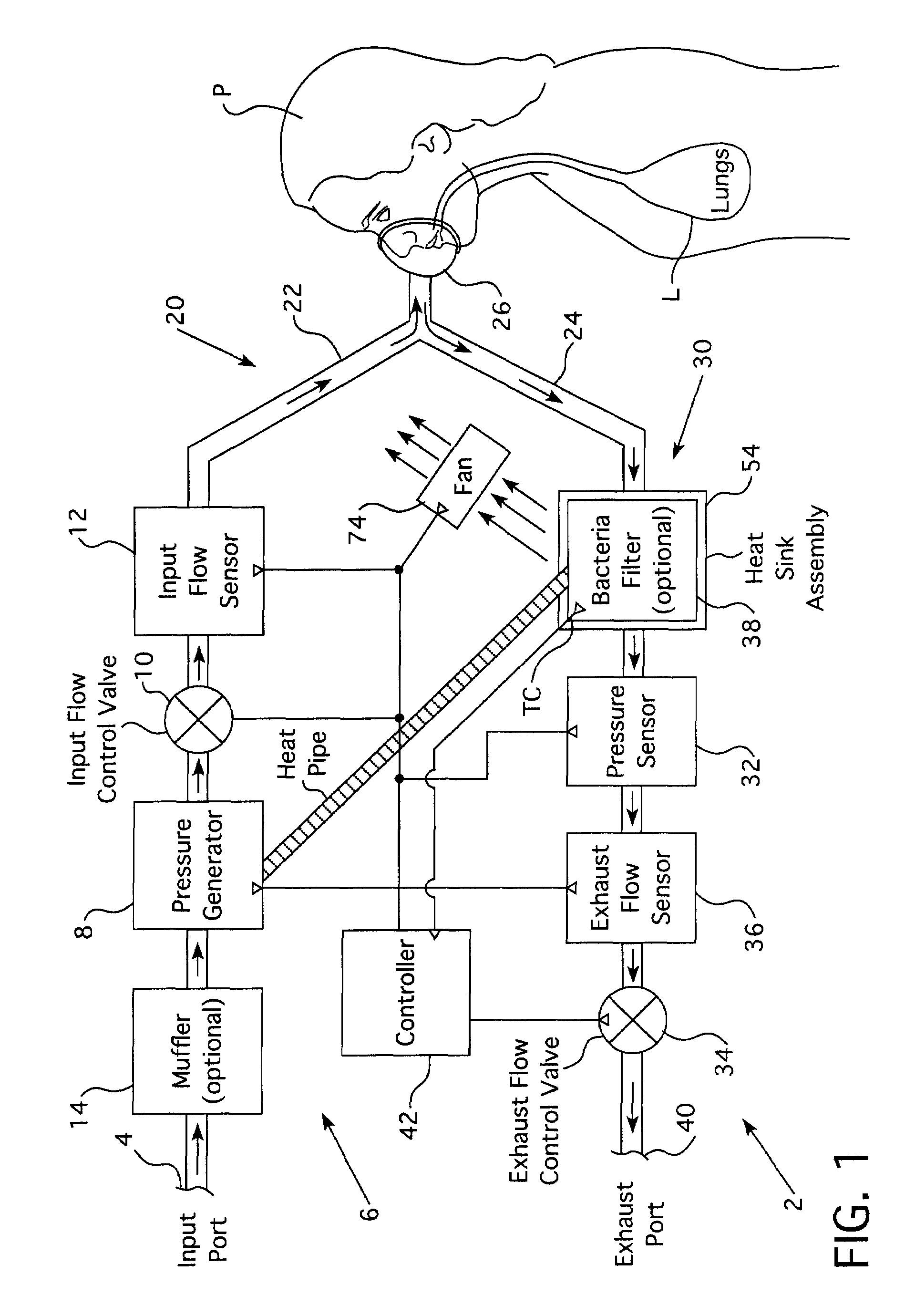
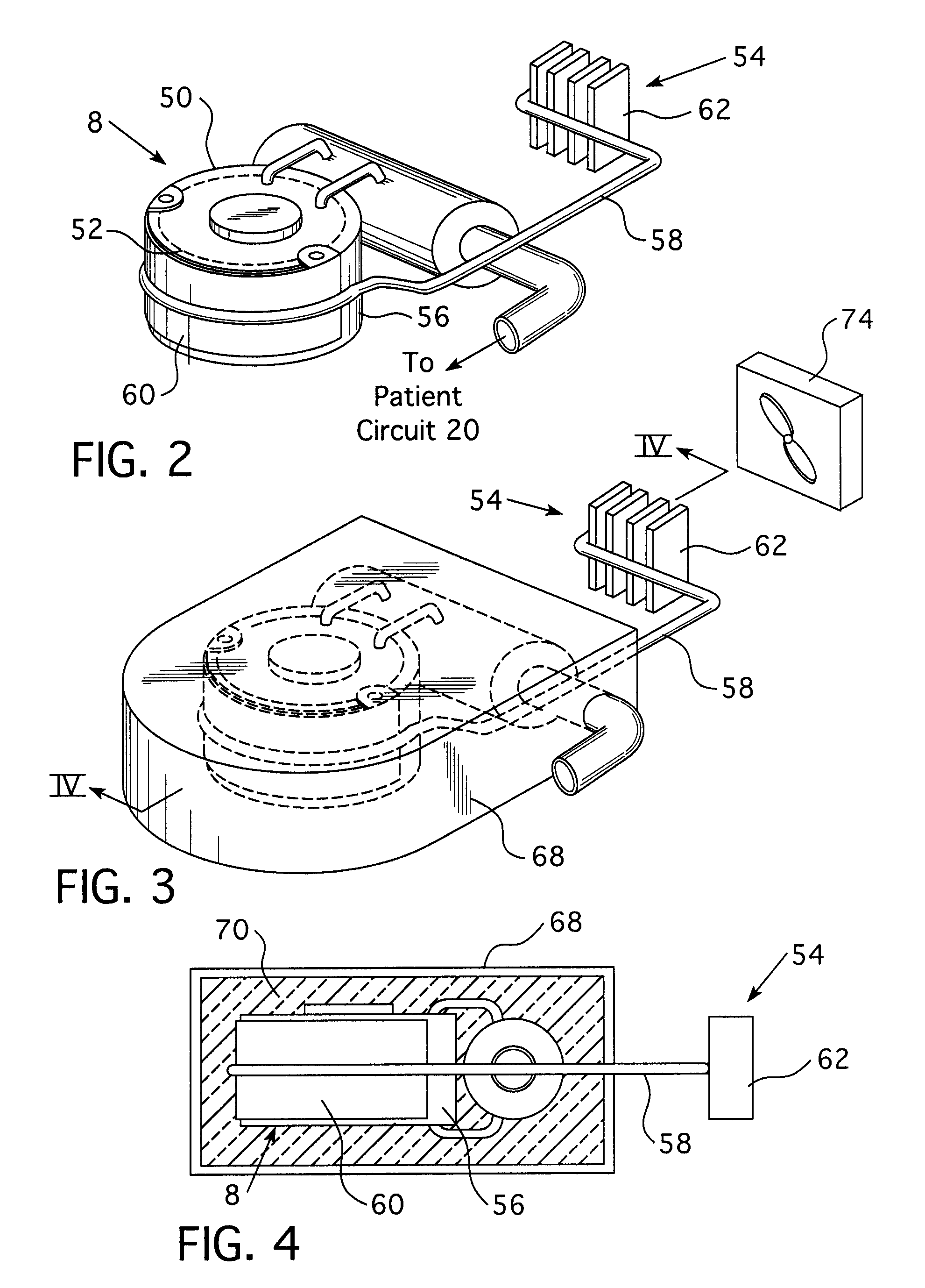
[0028]With reference to FIG. 1, a medical ventilator 2 includes an input port 4 for receiving a breathing gas, such as atmospheric air or any other suitable gas, for use by a patient P. Gas is drawn into input port 4 via a gas flow delivery system 6 that includes a pressure generator 8, an input flow control valve 10 and an input flow sensor 12. Optionally, gas flow delivery system 6 can include a muffler 14.

[0029]Pressure generator 8 is operative to elevate the pressure of the breathing gas received via input port 4. This pressurized breathing gas is provided to input flow control valve 10, which is operative to control a pressure or flow of pressurized breathing gas delivered to patient P. Input flow sensor 12 is operative for measuring the amount of fluid flowing therethrough and outputting a flow signal indicative thereof.

[0030]Gas flow delivery system 6 shows one desirable arrangement of pressure generator 8, input flow control valve 10, input flow sensor 12 and muffler 14. How...


PUM


Abstract

A medical ventilator includes a pressure generator for increasing a pressure of gas that produces heat during the operation thereof. A heat sink spaced from the pressure generator is provided for absorbing heat from the pressure generator. A bacteria filter requiring heating in excess of an ambient temperature for the effective operation thereof is coupled in thermal communication with the heat sink. A heat pipe is coupled in thermal communication with the heat sink and the pressure generator for conveying at least part of heat produced by the pressure generator to the bacteria filter via the heat sink.

Description

CROSS-REFERENCE TO RELATED APPLICATIONS[0001]This application claims priority under 35 U.S.C. § 119(e) from provisional U.S. patent application No. 60 / 435,112 filed Dec. 20, 2002 the contents of which are incorporated herein by reference.BACKGROUND OF THE INVENTION[0002]1. Field of the Invention[0003]The present invention pertains to a medical ventilator and, more particularly, to redistributing heat produced during operation of the medical ventilator.[0004]2. Description of Related Art[0005]Heretofore, medical ventilators included a pressure generator encapsulated in a suitable noise suppression material, such as foam, to muffle noise produced by the pressure generator during operation. While encapsulating the pressure generator in foam has the desired effect of muffling noise produced by the pressure generator, the foam also acts as an insulator that traps in the pressure generator heat produced thereby during operation. Because the pressure generator is utilized to increase the p...

Claims


Application Information

Patent Timeline
IPC IPC(8): A61M16/00A62B23/02A62B7/00A62B7/10F16K31/02F24J3/00
CPCA61M16/0057A61M16/1055A61M16/1065A61M16/204A61M16/205A61M2016/0027A61M2016/0039A61M2016/0042A61M2205/3368A61M2205/3633A61M2205/3666A61M2205/42A61M16/0858
Inventor NGUYEN, PATRICKKIMM, GARDNER J.HAN, STEVEARCILLA, MABINI M.
Owner RIC INVESTMENTS LLC
Why Eureka
Try Eureka