
Multi-functional umbrella

a multi-functional, umbrella technology, applied in the field of umbrellas, can solve the problems of not providing a means for misting or rinsing a user with water, not providing an integrated audio system, not providing an auger with which a user can use,

Inactive Publication Date: 2009-03-03
KLEIN JR ROLAND C +1
View PDF16 Cites 43 Cited by
  • Summary
  • Abstract
  • Description
  • Claims
  • Application Information

AI Technical Summary

Benefits of technology

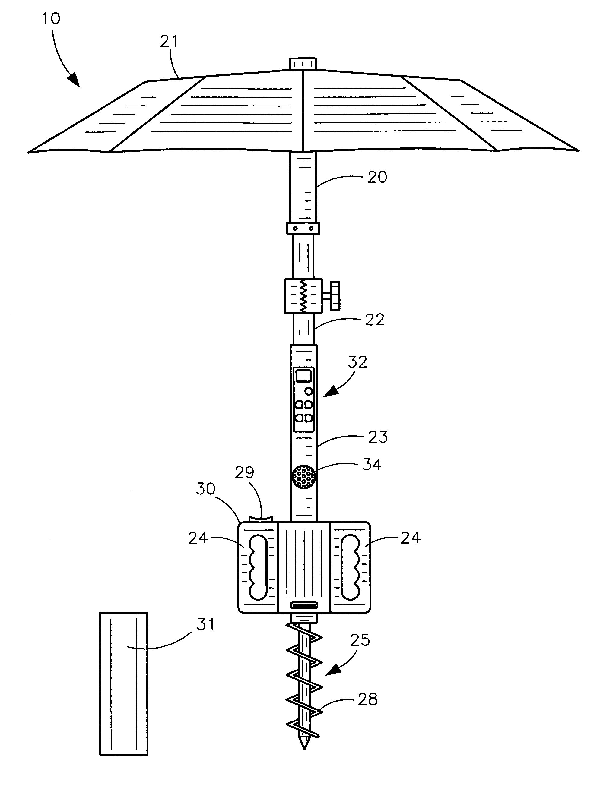
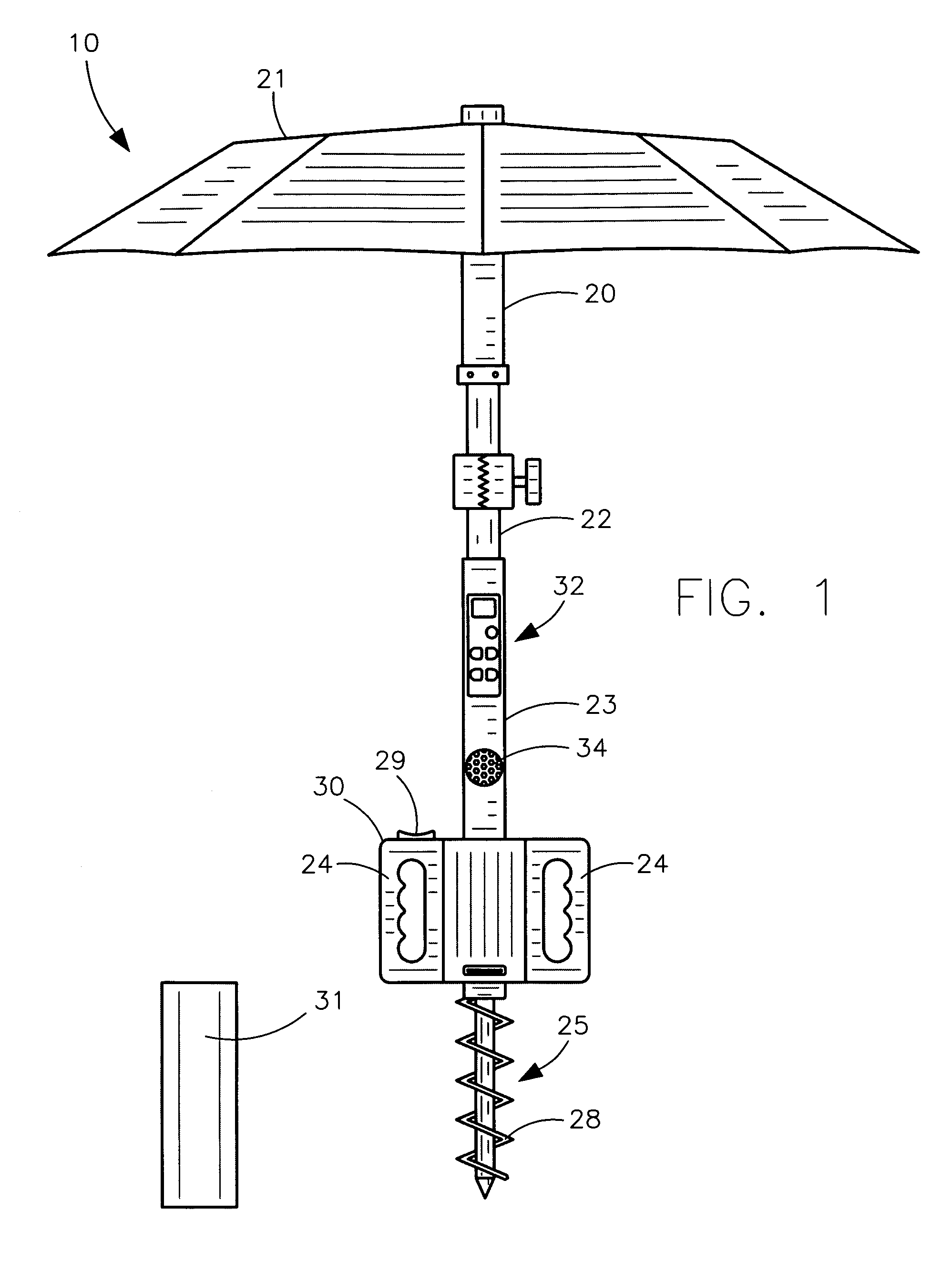
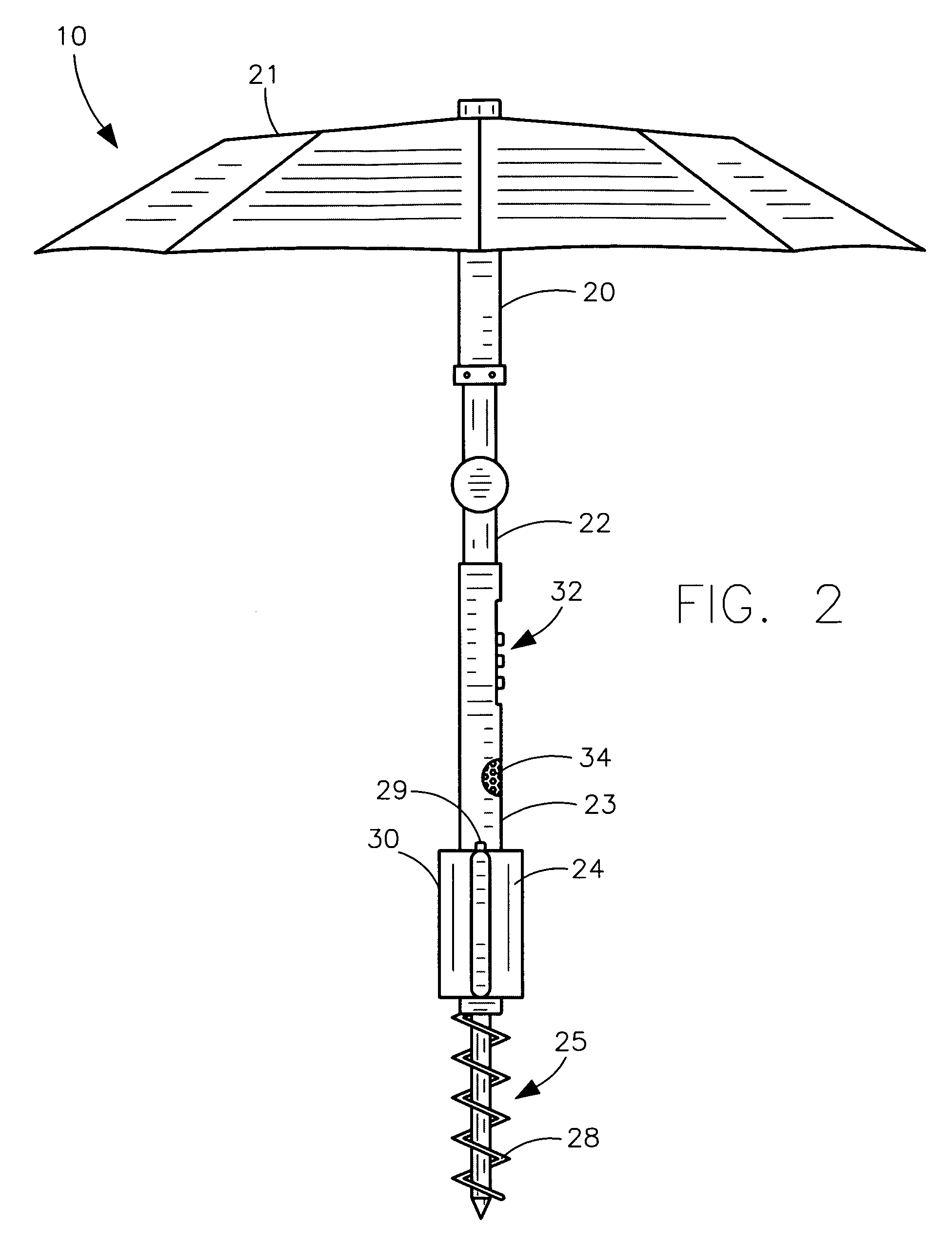
[0013]The apparatus further includes a mechanism for automatically penetrating the second rod beneath a ground surface such that the first rod conveniently remains statically anchored at a fixed position during operating conditions. Such an automatic penetrating mechanism includes a motor housed within the handle section, and a power source electrically coupled to the motor. An auger is directly coupled to the motor and effectively extends vertically downward therefrom. A switch is conveniently disposed along an outer surface of the handle section. A protective cap is removably positioned over the auger for effectively shielding the auger during transport, and the auger is advantageously rotatable about a fulcrum axis defined along a longitudinal length of the second rod.
[0015]The apparatus further includes a mechanism for discharging a predetermined quantity of fluid from the first rod. Such a fluid discharging mechanism includes a reservoir formed within the first rod and advantageously extending downwardly from an open top end of the first rod such that the top end effectively defines an inlet port for conveniently introducing water into the reservoir. A plurality of outlet ports is in fluid communication with the reservoir and disposed along a bottom end thereof. A protrusion is formed along an inner wall of the reservoir and at an entrance of the outlet ports, and is conveniently located above the outlet ports. A vertically displaceable stop member is linearly positioned within the reservoir and is selectively disengaged from the protrusion. An air pump is seated within the first rod and subjacent to the stop member, and an inflatable diaphragm is directly coupled to the air pump and removably abutted directly against a bottom surface of the stop member. The outer edge of the stop member is chamfered and effectively defines an arcuately shaped region that has a flexible diameter adaptable to a corresponding diameter of the protrusions for advantageously creating a water-tight seal therewith when the diaphragm is deflated. Such a diaphragm is selectively adaptable for receiving a volume of air therein.
[0016]The fluid discharging mechanism further includes a conduit directly coupled to the air pump and passing through the stop member. Such a conduit has a distal end terminating at a top surface of the stop member and within the reservoir. The air pump effectively causes the diaphragm to inflate and thereby elevates the stop member a predetermined vertical distance such that outer edges of the stop member advantageously disengage the protrusion and thereby conveniently allows the fluid to flow along a downward passageway into the outlet ports. The conduit introduces air into the reservoir and thereby effectively causes the fluid to rapidly discharge outwardly from the outlet ports for creating a mist. The automatic penetrating mechanism and the broadcasting mechanism and the fluid discharging mechanism are simultaneously and independently operable as desired by the user.
[0021]The air pump causes the diaphragm to inflate and thereby elevates the stop member a predetermined vertical distance such that outer edges of the stop member disengage the protrusion and thereby allows the fluid to flow along a downward passageway into the outlet ports. The conduit introduces air into the reservoir and thereby causes the fluid to rapidly discharge outwardly from the outlet ports for creating a mist.

Problems solved by technology

Unfortunately, this prior art example does not provide means for misting or rinsing a user with water, and also does not provide an integrated audio system whereby a user can listen to music without having to carry an additional item.
Unfortunately, this prior art example does not provide an auger with which a user can easily insert the umbrella into a ground surface.
In addition, this prior art example also does not provide means for misting or rinsing a user with water, and also does not provide an integrated audio system whereby a user can listen to music without having to carry an additional item.

Method used


Image

  • Multi-functional umbrella
  • Multi-functional umbrella
  • Multi-functional umbrella

Examples


Embodiment Construction

[0033]The present invention will now be described more fully hereinafter with reference to the accompanying drawings, in which a preferred embodiment of the invention is shown. This invention may, however, be embodied in many different forms and should not be construed as limited to the embodiment set forth herein. Rather, this embodiment is provided so that this application will be thorough and complete, and will fully convey the true scope of the invention to those skilled in the art. Like numbers refer to like elements throughout the figures.

[0034]The apparatus of this invention is referred to generally in FIGS. 1-7 by the reference numeral 10 and is intended to provide a multi-functional umbrella. It should be understood that the apparatus 10 may be used to provide shade, mist, and audio sounds in many different types of environments and should not be limited in use to providing shade, mist, and audio sounds in only those types of environments described herein.

[0035]Referring to...


PUM


Abstract

A multi-functional umbrella includes a first rod and a collapsible canopy directly anchored thereto. A second rod is pivotally attached to the first rod, and a handle section is monolithically formed with the second rod and spaced from the first rod. A mechanism automatically penetrates the second rod beneath a ground surface. A mechanism broadcasts audio signals and is housed within the second rod and the handle section, and includes a radio and a speaker electrically coupled thereto. A mechanism discharges a predetermined quantity of fluid from the first rod. The automatic penetrating mechanism and the broadcasting mechanism and the fluid discharging mechanism are simultaneously and independently operable as desired by the user.

Description

CROSS REFERENCE TO RELATED APPLICATIONS[0001]This application claims the benefit of U.S. Provisional Application No. 60 / 762,996, filed Jan. 30, 2006, the entire disclosures of which are incorporated herein by reference.STATEMENT REGARDING FEDERALLY SPONSORED RESEARCH OR DEVELOPMENT[0002]Not Applicable.REFERENCE TO A MICROFICHE APPENDIX[0003]Not Applicable.BACKGROUND OF THE INVENTION[0004]1. Technical Field[0005]This invention relates to umbrellas and, more particularly, to a self-standing multi-functional umbrella for providing user enjoyment during inclement weather conditions.[0006]2. Prior Art[0007]Beach umbrellas are widely used not only on the beach to provide shade from the direct light of the sun but also on other outdoor recreational places, such as the areas for the spectators of a sport and outdoor coffee shops, such that people sitting under them can be protected from the sun and rain. Beach umbrellas usually include a shank, several ribs radially spread out from the uppe...

Claims


Application Information

Patent Timeline
IPC IPC(8): A45B3/00
CPCA45B3/00E04H12/2223A45B2017/005A45B2200/1045
Inventor KLEIN, JR., ROLAND C.CONN, MIKE
Owner KLEIN JR ROLAND C
Learn More