Securement mechanism

a technology of secure mechanism and end cap, which is applied in the direction of load securing, threaded fasteners, transportation items, etc., can solve the problems of physical removal of users, loss of end caps, damage, etc., and reduce the overall length of rail available for us

Inactive Publication Date: 2009-03-03
SPORTRACK
View PDF19 Cites 27 Cited by
  • Summary
  • Abstract
  • Description
  • Claims
  • Application Information

AI Technical Summary

Benefits of technology

[0009]The pin and actuating member are threadingly engaged with one another such that rotation of the actuating member moves the pin and attached locking plate up and down. To prevent the pin from rotating at the same time, the actuating member is rotated, it typically includes at least a partial noncircular cross-section. The mating portion of the housing includes a noncircular feature that complements the noncircular cross-section of the pin to the extent that rotation of the pin within the housing is minimized as the actuating member is rotated.

Problems solved by technology

A problem with this approach is that a user has to physically remove a component to allow for installation of the cleat.
The end cap may be lost, become damaged, or be difficult to reinstall.
Moreover, the end of the rail must be accessible, typically reducing the overall length of rail available for use.
Further, under some circumstances, if the cleat becomes unsecured or creeps along the rail, it can suddenly escape from a notch.

Method used


Image

  • Securement mechanism
  • Securement mechanism
  • Securement mechanism

Examples


Embodiment Construction

[0033]Referring now to the drawings, exemplary embodiments are shown in detail. Although the drawings represent exemplary embodiments, the drawings are not necessarily to scale and certain features may be exaggerated. Further, the embodiments set forth herein are not intended to be exhaustive or otherwise limit or restrict the invention to the precise forms and configurations shown in the drawings and disclosed in the following detailed description.

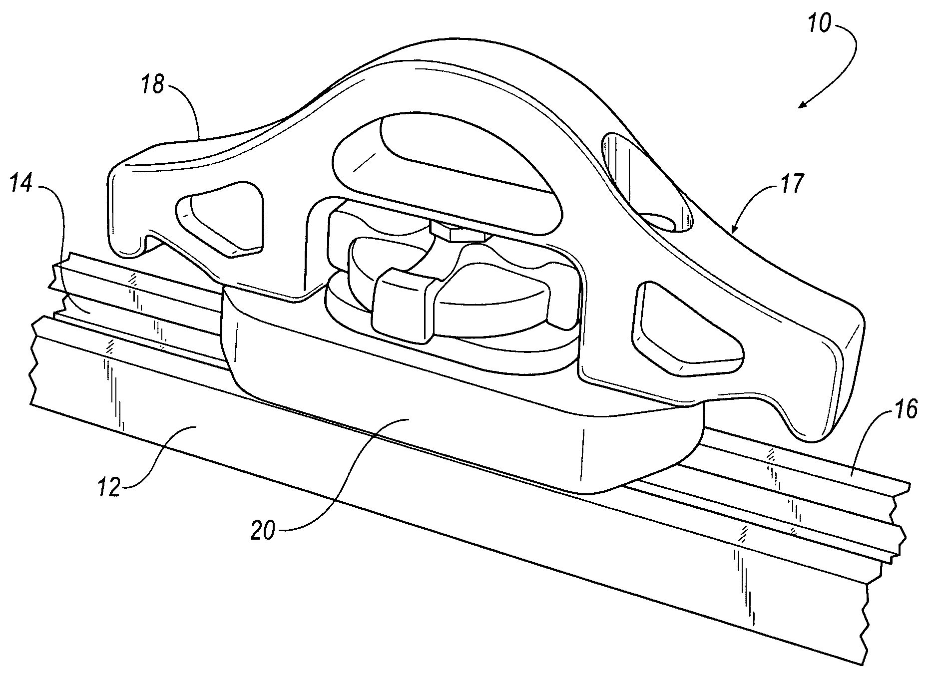
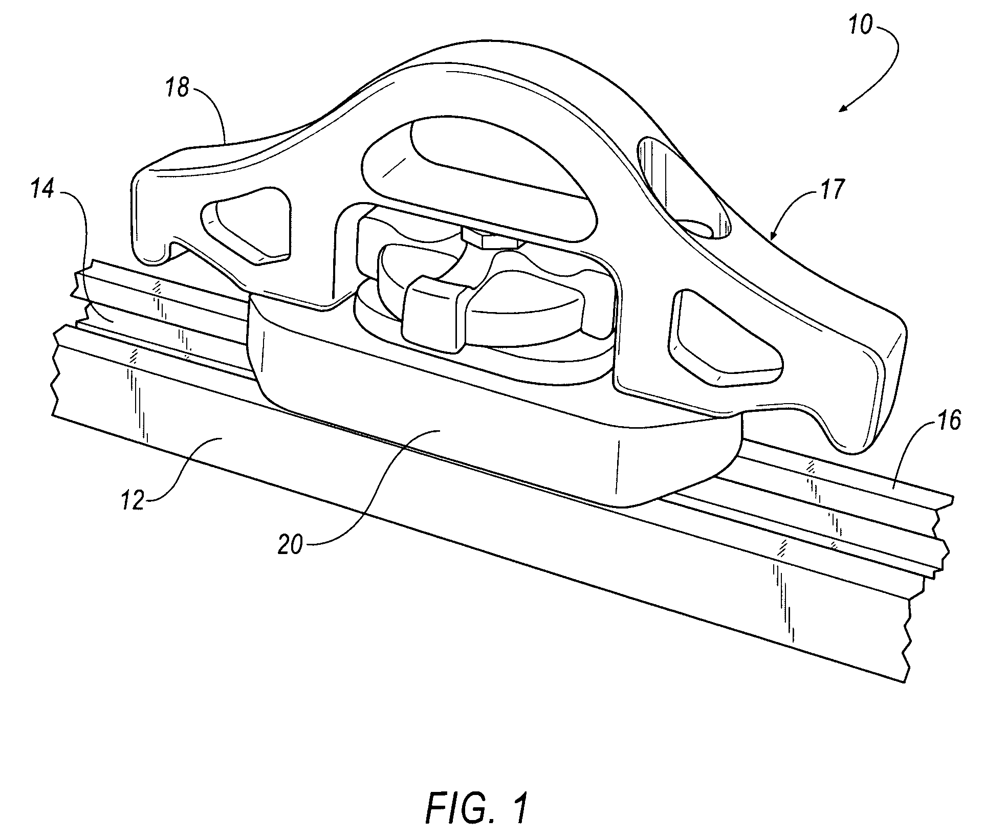
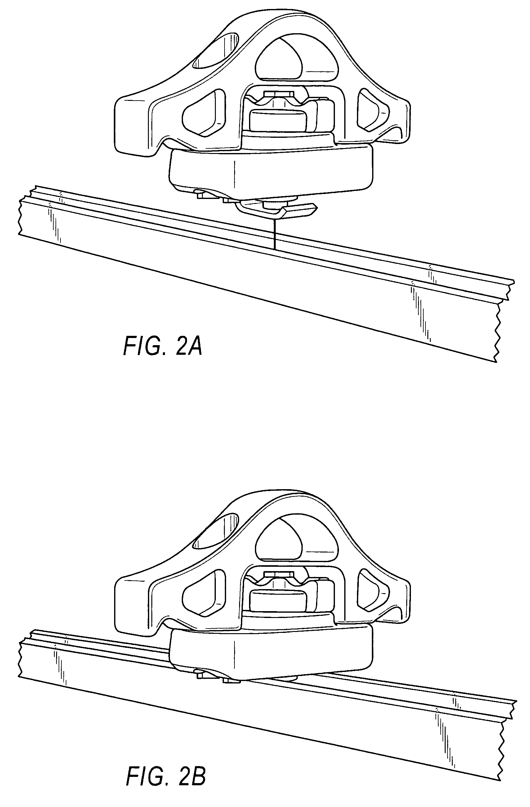
[0034]FIGS. 1-7 are directed to an innovative securement mechanism including a tie-down cleat assembly 10 and mating component in the form of a locking member or rail 12.

[0035]Rail 12 is formed with a continuously extending channel 14 along its length. The channel 14 of the rail 12 is defined by a web or bottom surface 50 disposed between opposing siderails 52, legs 54 extending into the channel from a free end of each siderail (as best shown in FIG. 6). An end cap (not shown) may be permanently secured to the rail 12, which may or may no...


PUM


Abstract

A securement mechanism includes a tie-down cleat assembly for engagement with a mating component, the tie-down cleat assembly including a pin, a lock plate adjacent to one of the ends of the pin, and a housing having an aperture receiving the pin. An actuating member is operationally connected to the pin and causes selective movement of the pin and lock plate between a secured and unsecured orientation. The lock plate has a first dimension permitting the lock plate to be inserted into a channel associated with the mating component and a second dimension permitting the securement of the mating component between the housing and locking plate. The pin and locking plate and preferably the housing are all rotatable as a single unit.

Description

RELATED APPLICATIONS[0001]The disclosures of U.S. Provisional Application No. 60 / 463,291, filed Apr. 16, 2003; U.S. patent application Ser. No. 11 / 101,984, filed Apr. 8, 2005; and U.S. patent application Ser. No. 10 / 825,456, filed Apr. 15, 2004 are herein incorporated by reference in their entireties, including their specifications, claims, and drawings.FIELD OF TECHNOLOGY[0002]The embodiments described herein are directed to an innovative tie-down cleat assembly loaded onto a rail or any vehicle surface and secured in position.BACKGROUND[0003]Tie-down cleats are commonly used with rails having channels defined by sidewalls and a bottom surface disposed between the sidewalls. The top of each sidewall typically has an inwardly extending leg disposed above the bottom surface. The tie-down cleat is disposed along a rail with a portion of the tie-down cleat including a lock plate being received within the channel, and movement being selectively constrained through interaction of the cle...

Claims


Application Information

Patent Timeline
Patent Type & Authority Patents(United States)
IPC IPC(8): B61D45/00B60P7/08F16B37/04
CPCB60P7/0815F16B37/045
Inventor HARBERTS, JOHN H.KLINKMAN, JOHN E.
Owner SPORTRACK
Why Eureka
Try Eureka