Method and apparatus for monitoring the integrity of components and structures

a technology for integrity monitoring and components, applied in the direction of fluid tightness measurement, structural/machine measurement, instruments, etc., can solve the problems of easy ingress of moisture, cracking, corrosion and disbonding of structures and components,

Inactive Publication Date: 2009-03-10
STRUCTURAL MONITORING SYST
View PDF33 Cites 7 Cited by
  • Summary
  • Abstract
  • Description
  • Claims
  • Application Information

AI Technical Summary

Problems solved by technology

These structures and components are difficult to examine for the detection of cracking, corrosion and disbonding.
Further they are prone to the ingress of moisture arising for various reasons including: capillary action and the substantially hollow nature of the structures, particularly those made from composite materials; exposure to temperature extremes; exposure to large ambient pressure variations; exposure to environments of high humidity and precipitation.
Apart from corrosion in metallic structure, the ingress of moisture can lead to serious structural flaws such as disbanding due to progressive damage caused by the cyclic intrusion of the moisture followed by expansion as it freezes.
Of course the above problems are not the exclusive domain of aircraft designers.

Method used


Image

  • Method and apparatus for monitoring the integrity of components and structures
  • Method and apparatus for monitoring the integrity of components and structures
  • Method and apparatus for monitoring the integrity of components and structures

Examples


Embodiment Construction

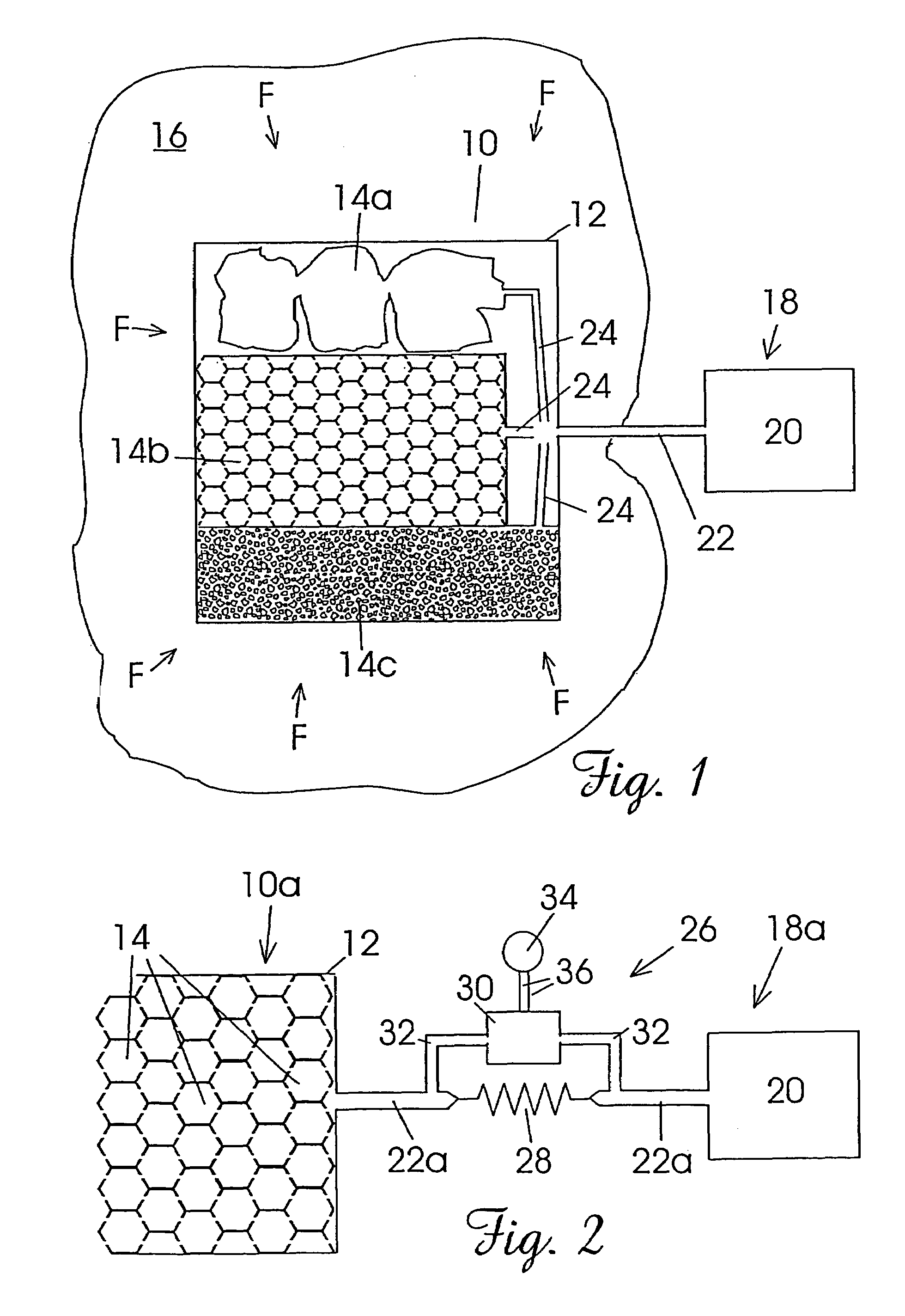
[0039]FIG. 1 illustrates schematically, one embodiment of a method and apparatus of the present invention for preventing the ingress of a fluid F into a structure 10. The structure 10 is a fictitious structure made up from three types of composite structure and is provided merely for the purpose of illustrating the principles of embodiments of the invention. The structure 10 has an outer skin 12 and a plurality of internal cavities 14a, 14b and 14c (hereinafter referred to in general as “cavities 14”). The actual geometry of the cavities 14 is a function of the type of structure 10. Cavities 14a are illustrative of a structure 10 having internal cavities of a random configuration; cavities 14b are illustrative of a structure 10 having a honeycomb or cellular-type core; and cavities 14c are illustrative of a structure 10 having a foam core.

[0040]The structure 10 is disposed in an environment 16 containing fluid F at an ambient pressure that acts on the structure 10. For example, the ...


PUM


Abstract

A method for monitoring the integrity of a permeable structure that is disposed in an environment containing a fluid at ambient pressure is provided. At least one cavity is formed in or on the permeable structure. A source of first fluid is provided at a first pressure greater than the ambient pressure. The cavity is coupled to the source through a high-fluid-flow impedance to establish a flow of the first fluid through the permeable structure via the cavity. A rate of flow of the first fluid through the permeable structure is allowed to stabilize to a steady-state rate. A change in the steady-state flow rate of the first fluid through the permeable structure is monitored.

Description

CROSS-REFERENCE TO RELATED APPLICATION[0001]This application is a continuation-in-part of application Ser. No. 09 / 905,681, filed Jul. 13, 2001, which is now abandoned.FIELD OF THE INVENTION[0002]The present invention is for a method and apparatus for monitoring the integrity of a component or structure, in particular though not exclusively, by monitoring a pressure state that can be maintained within cavities either inherently provided or specifically formed in the component or structure.BACKGROUND OF THE INVENTION[0003]The present invention has its genesis from consideration of the problems faced by aircraft designers in monitoring the integrity of: sandwiched structures typically encountered around splices and cut-outs in fuselages; and, substantially hollow components as encountered in composite structures such as flaps, doors, panels and the like; and, attempting to prevent the ingress of moisture into such structures and components. These structures and components are difficult...

Claims


Application Information

Patent Timeline
Patent Type & Authority Patents(United States)
IPC IPC(8): G01M3/26
CPCG01M3/2869G01M3/3236G01M5/00G01M5/0033G01N15/08
Inventor DAVEY, KENNETH JOHN
Owner STRUCTURAL MONITORING SYST
Why Eureka
Try Eureka