Roll motion damping device for a floating body

a floating body and rolling motion technology, applied in the field of rolling motion damping devices for floating bodies, can solve the problems of increasing requiring increased power, so as to reduce the weight of the floating vessel, increase the viscous drag resistance, and reduce the effect of rolling motion

Inactive Publication Date: 2009-03-10
ZENTECH
View PDF6 Cites 24 Cited by
  • Summary
  • Abstract
  • Description
  • Claims
  • Application Information

AI Technical Summary

Benefits of technology

[0006]There are two primary ways in which roll motion may be resisted: inertial resistance and viscous drag resistance. Inertia describes a body's tendency to resist changes in its motion (or as generally described in science texts, inertia is the tendency of a body at rest to stay at rest and a body in motion to stay in motion in the same direction at the same velocity), and it is proportionate to the mass of the body at issue. So, one way to increase a floating vessel's resistance to roll is to increase the vessel's mass moment of inertia.
[0007]By increasing a floating vessel's effective mass, the vessel's mass moment of inertia can be increased. This would dampen the effect of rolling motion introduced by waves by using the vessel's own inertial tendency to resist a change in its motion. This innate tendency can be amplified by increasing the vessel's mass. But there can be negative side effects to permanently increasing a floating vessel's mass. For example, increased mass could require increases in power in order to propel the vessel, as well as additional construction costs.
[0008]The embodiments disclosed below do not directly increase the material mass of the floating vehicle itself; instead they employ sponsons, located on either side of the vessel, to temporarily increase the vessel's virtual mass in response to wave roll motion. A sponson is an outboard projection from the side of a floating vessel that traps a portion of the surrounding water, adding this additional water mass to the vessel's effective mass in order to increase the vessel's overall mass moment of inertia. So, by enclosing water within a sponson rigidly joined to a floating vessel, the vessel's inertial resistance to roll can be increased hydrodynamically. The value of the inertial resistance is the product of the added mass moment of inertia and the corresponding angular acceleration in roll. This term acts as an external moment exerted by the water and has a phase lag of 180 degrees in conjunction with the roll angular acceleration itself. In other words, it acts against the roll acceleration.
[0011]The embodiments disclosed below can use either or both of these general techniques to resist roll. Often, inertial resistance and viscous drag resistance can be used in conjunction, maximizing a floating vessel's overall resistance to roll. When a keel is called for by a particular design, the disclosed embodiments tend to make use of a wing keel, rather than a conventional bilge keel, which is attached to the hull. A wing keel is an underwater fin that has an angled foil that projects out more towards the horizontal plane. A wing keel can be used in conjunction with a sponson, while a conventional bilge keel cannot. In fact, a wing keel can improve the effectiveness of a sponson and baffles in resisting roll motion. And the wing keel itself provides greater resistance to roll motion than does the conventional bilge keel. The disclosed embodiments also demonstrate the effectiveness of using multiple baffles within each sponson. This practice can increase the inertial resistance provided by the sponson, by trapping additional water within the sponson, as well as providing additional surfaces for viscous drag to counteract the roll motion.

Problems solved by technology

But there can be negative side effects to permanently increasing a floating vessel's mass.
For example, increased mass could require increases in power in order to propel the vessel, as well as additional construction costs.

Method used


Image

  • Roll motion damping device for a floating body
  • Roll motion damping device for a floating body
  • Roll motion damping device for a floating body

Examples


Embodiment Construction

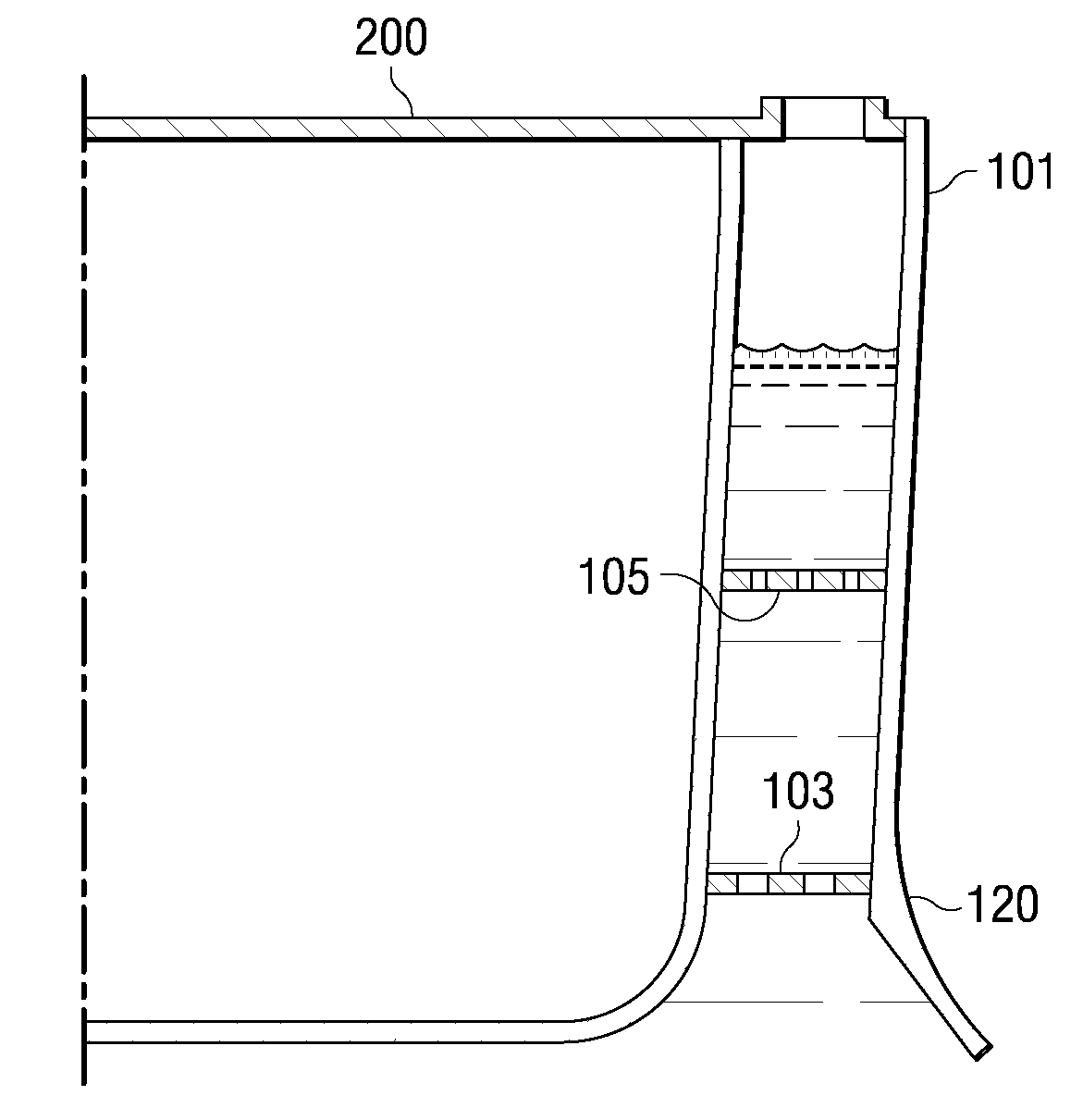
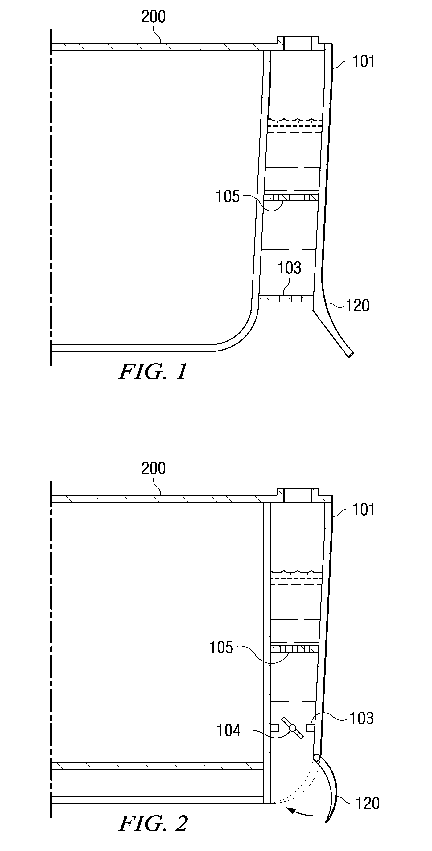
[0018]The disclosed embodiment shown in FIG. 1 represents half of a cross-section of a floating vessel 200 with both a sponson 101, including multiple internal baffles 103 and 105, and a wing keel 120. In operation, the other side of the floating vessel 200 would typically be a mirror image of that shown in FIG. 1, so that any anti-roll devices would operate in a complementary fashion on both sides of the vessel 200. In FIG. 1, sponson 101 is rigidly attached to the hull of the floating vessel 200. The sponson 101 is a relatively thin (with respect to the cross-sectional width of the vessel 200) projection that extends upward from the bottom of the vessel 200 to above the waterline. The sponson 101 is open on the bottom, allowing water to enter into the cavity formed by the sponson 101 next to the vessel's hull 200, and in the embodiment illustrated in FIG. 1, the top of the sponson 101 opens to atmosphere. In this particular embodiment, the sponson 101 would typically run approxima...


PUM


Abstract

The present disclosure relates to techniques for reducing roll motion experienced by a floating vessel. The disclosure reveals several different techniques for damping roll motion, which may be used alone or in conjunction to stabilize a floating vessel. A typical disclosed embodiment of a roll motion damping device would employ a sponson on each side of the vessel. Each sponson would typically encompass one or more baffles. And a wing keel could be located on the outside of each sponson. When all of these features are used in conjunction, they work synergistically to maximize the resistance to roll experienced by the floating vessel.

Description

CROSS-REFERENCE TO RELATED APPLICATIONS[0001]This application claims the benefit of U.S. Provisional Application No. 60 / 763,293, filed on Jan. 30, 2006. U.S. Provisional Application No. 60 / 763,293 is commonly assigned with the present application and is hereby incorporated by reference for all purposes.TECHNICAL FIELD[0002]The embodiments described below relate generally to techniques for dampening roll motion induced on boats, ships, and other floating bodies / vessels by wave action.BACKGROUND[0003]Waves are a fact of life for all floating bodies / vessels. From ocean-going ships, barges, and floating oil platforms to freshwater boats and canoes, all floating vessels are impacted by waves. As a result, one of the main design characteristics for any floating vessel is stability. Stability is important not only because it affects the comfort of passengers and crew (by reducing the sensation of movement that can lead to motion-sickness, for example), but also because it affects safety. A...

Claims


Application Information

Patent Timeline
Patent Type & Authority Patents(United States)
IPC IPC(8): B63B41/00
CPCB63B39/03B63B39/06B63B2039/067
Inventor CHIU, HIN
Owner ZENTECH
Why Eureka
Try Eureka