Air spring/coil spring combination suspension system

a suspension system and coil spring technology, applied in the direction of resilient suspensions, vehicle springs, vehicle components, etc., can solve the problems of air springs, and hence the ride, to be stiff, reduce the comfort of occupants, and general perception of ride stiffness, so as to achieve the effect of convenient manufacturing

Inactive Publication Date: 2009-03-10
TLC SUSPENSIONS
View PDF7 Cites 15 Cited by
  • Summary
  • Abstract
  • Description
  • Claims
  • Application Information

AI Technical Summary

Benefits of technology

[0035]These and other objects of the invention are accomplished by providing a method for improving ride, handling, and load-carrying capability of a vehicle. A vehicle is provided having opposing side frame members, a rear axle and a leaf spring suspension with a supplemental suspension system comprised of a plurality of spring assemblies, each spring assembly of the plurality of spring assemblies comprising, in combination, a coil spring attached to an air spring arranged around a common central axis and attached by retainer means, which is mounted above the rear axle of the vehicle; an upper support member which extends between the opposing side frame members, which is attached thereto using Z-brackets, and which supports one of the air spring or the coil spring of respective spring assemblies; and a lower support member which is positioned above the rear axle, which extends between respective leaf springs of the pair of leaf springs, which is fixedly mounted to the respective leaf springs, and which supports one of the air spring or the coil spring of respective spring assemblies. Respective air springs of the plurality of spring assemblies may be partially inflated thereby causing respective coil springs of the plurality of spring assemblies to partially collapse into their housings when improvement to the ride is desired in combination with improvement in load-carrying ability. Finally, respective air springs of the plurality of spring assemblies may be completely inflated thereby causing respective coil springs of the plurality of spring assemblies to substantially completely collapse into their housings when improvement in the ride and maximum load-carrying ability are desired.

Problems solved by technology

These systems typically require very high air pressure which causes the air springs, and hence the ride, to be stiff.
While systems employing air springs provide additional lift advantageous for carrying or towing heavy loads, the stiffness of the ride is generally perceived as reducing the comfort of the occupants.
Thus, air spring suspension systems provide lift when heavily loaded but at the expense of the comfort of the occupants which may not be justified during operation of the vehicle without heavy loads.
Generally, suspension systems strong enough to provide sufficient lift when loaded make the ride stiffer during unloaded operation, while suspension systems that don't interfere with unloaded operation may not be strong enough to provide sufficient lift when loaded.
Additionally, there is often insufficient space in most vehicles for more than one suspension system.
While some systems are quite simple and easily added to existing vehicles, others require significant modifications to the standard “original equipment manufacturer” (OEM) product and / or require complicated installation.

Method used


Image

  • Air spring/coil spring combination suspension system
  • Air spring/coil spring combination suspension system
  • Air spring/coil spring combination suspension system

Examples


Embodiment Construction

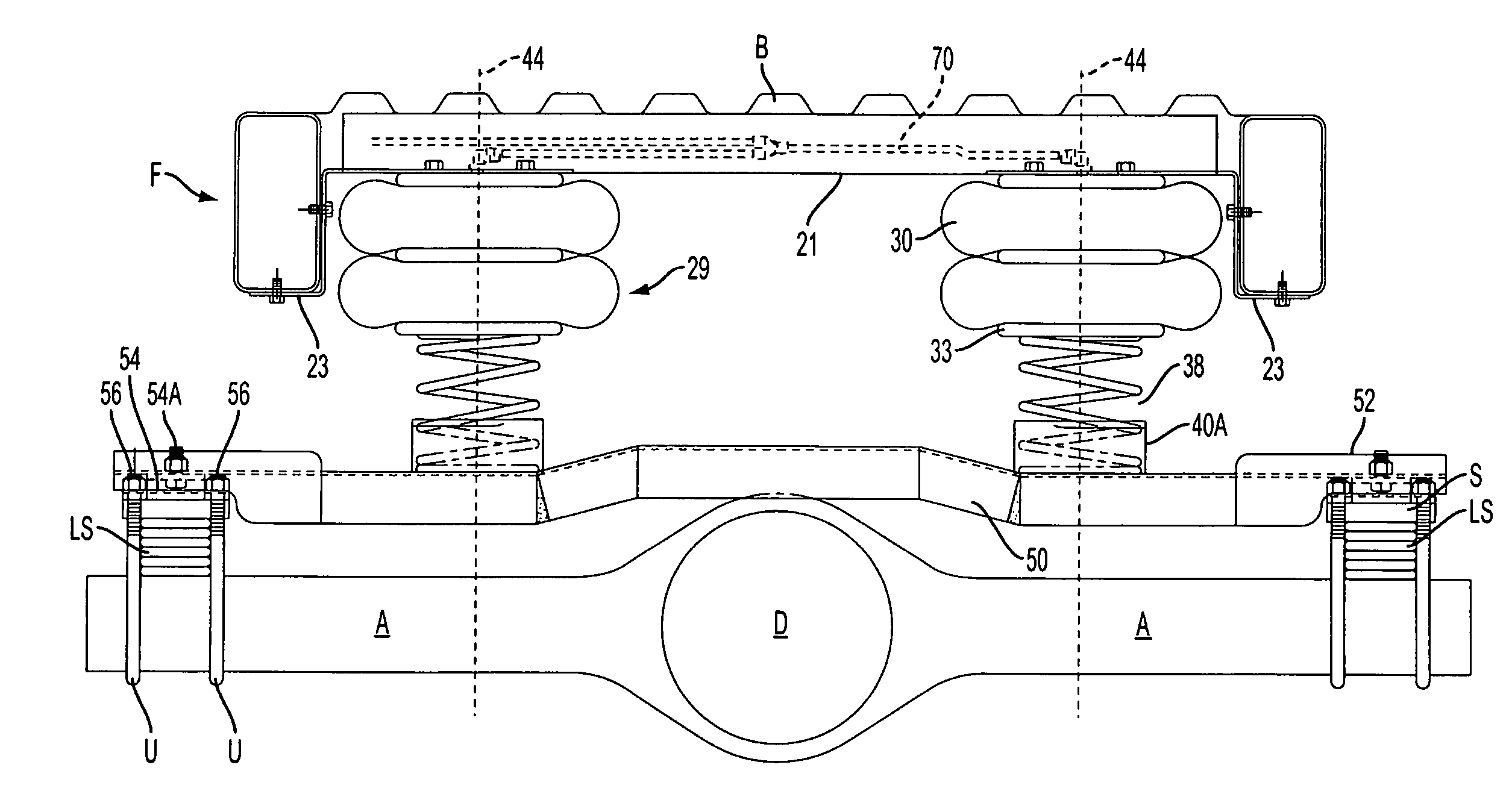
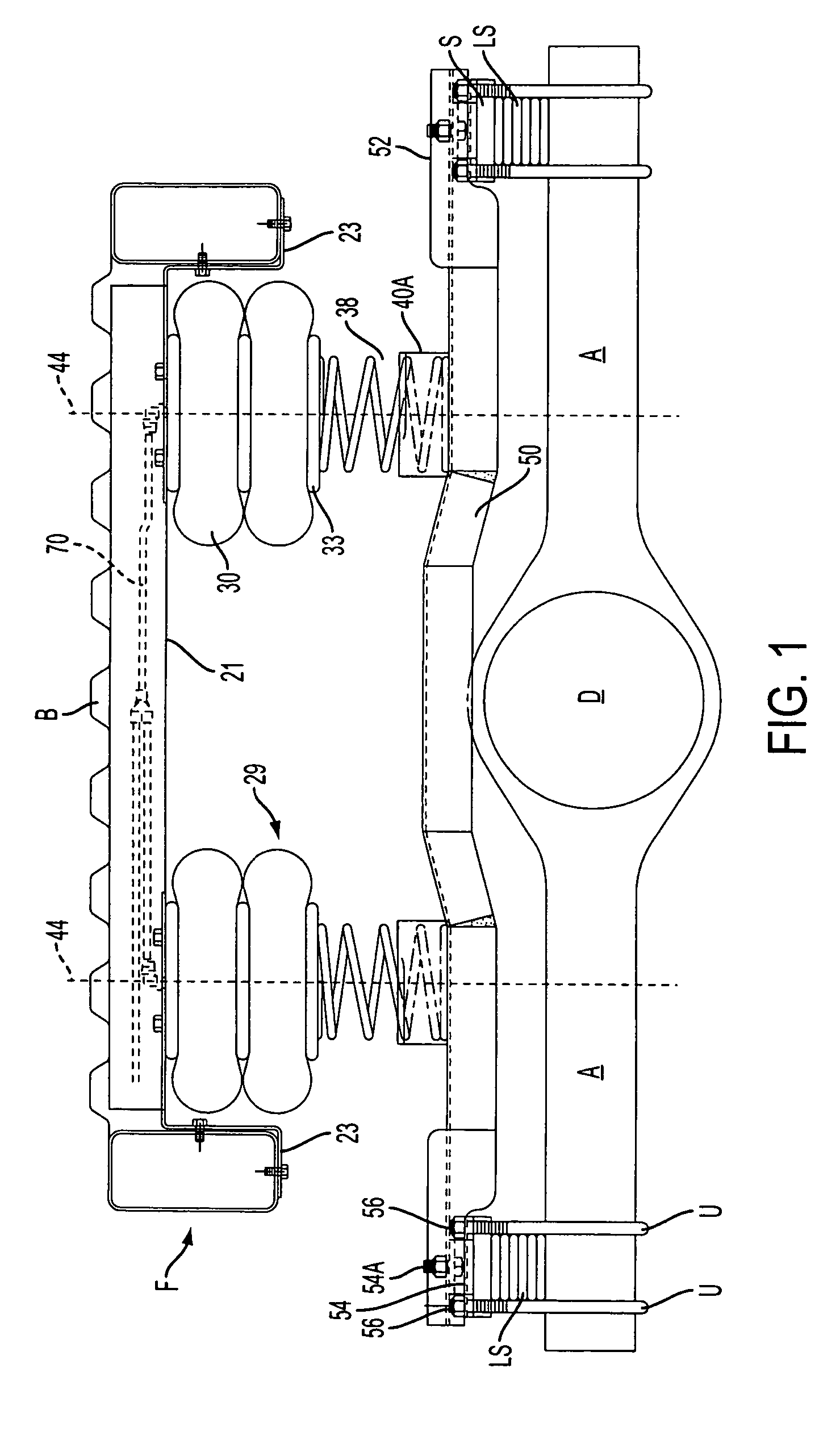
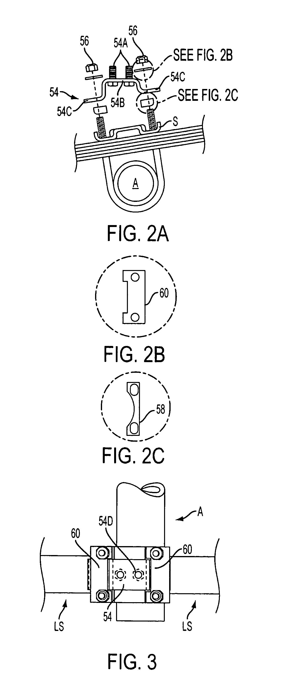
[0051]With reference to FIG. 1 herein, the present improvement to the prior Mullican invention provides a lower support member 50 that is positioned above rear axle A but does not touch it or come to rest upon it. Instead, lower support member 50 is attached on top of existing leaf springs LS using a lower support end bracket 54 in conjunction with the same OEM U-bolt U, shackles S, and nuts 56, and optionally pads and / or spacers, that attach leaf spring LS to the vehicle's chassis and frame. While FIGS. 1 and 4 show the leaf springs LS occupying completely the space between rear axle A and shackle S, some manufactures supply pads and / or spacers on top of rear axles. Thus, FIGS. 2A, 8, 9, and 11 show a gap between the rear axle and the leaf spring which could be occupied by a pad and / or spacer, but which have not been shown in these figures. Indeed, FIG. 7A does not show the leaf springs or any pads and / or spacers in order to keep this figure simple. As used herein, the term “shackl...


PUM


Abstract

A supplemental suspension system for a vehicle having a rear axle and a leaf spring suspension system including a pair of leaf springs mounted over respective ends of the rear axle, the supplemental suspension system including a lower support member which is positioned above the rear axle, which extends between respective leaf springs of the pair of leaf springs, and which is fixedly mounted to respective leaf springs of the pair of leaf springs; and a plurality of spring assemblies which are mounted above the rear axle, each spring assembly of the plurality of spring assemblies being composed of, in combination, a coil spring and an air spring arranged around a common central axis and attached by a retainer, wherein the plurality of spring assemblies are supported by the lower support member.

Description

CROSS-REFERENCE TO RELATED APPLICATIONS[0001]This Application for U.S. Letters Patent claims the benefit of the priority of Provisional Application No. 60 / 651,177 filed Feb. 8, 2005, and Provisional Application No. 60 / 696,581 filed Jul. 1, 2005, the disclosures of which are incorporated herein by reference. These Provisional Applications disclose improvements to the invention disclosed in Provisional Patent Application No. 60 / 629,682 filed on Nov. 18, 2004, now U.S. application Ser. No. 11 / 281,606 filed Nov. 18, 2005, by Vernon Jeffrey Mullican titled AIR SPRING / COIL SPRING COMBINATION SUSPENSION SYSTEM, the disclosures of which are herein incorporated by reference.BACKGROUND OF THE INVENTION[0002](1) Field of the Invention[0003]This invention relates to suspension systems for vehicles. As used herein, the terms “vehicle” and “vehicles” are intended to include but not be limited to passenger cars, sport utility vehicles, pick-up trucks, commercial trucks, buses, vans, recreational v...

Claims


Application Information

Patent Timeline
Patent Type & Authority Patents(United States)
IPC IPC(8): B60G11/58
CPCB60G9/00B60G9/003B60G11/36B60G11/465B60G11/58B60G2200/31B60G2202/112B60G2202/12B60G2202/152B60G2204/121B60G2204/124B60G2204/126B60G2204/15B60G2204/43B60G2206/911
Inventor MULLICAN, VERNON JEFFREYRAWN, RAYMOND CHARLES
Owner TLC SUSPENSIONS
Why Eureka
Try Eureka