Positioning of a magnetic head in a magnetic data recording device using a multiple sensor array

a technology of magnetic head and array, applied in the field of magnetoresistive sensors, can solve the problems of increasing sensor noise, unable to achieve further reduction in size, and the sensor is rapidly approaching a limit beyond, and achieves significant increments in the density of the areal, high spatial resolution of the sensor elements, and high magnetoresistive response.

Inactive Publication Date: 2009-03-10
HITACHI GLOBAL STORAGE TECH NETHERLANDS BV
View PDF19 Cites 26 Cited by
  • Summary
  • Abstract
  • Description
  • Claims
  • Application Information

AI Technical Summary

Benefits of technology

[0012]The present invention provides a system for providing a Position Error Signal (PES) on a continuous basis using a data track, without the need for a separate servo track or servo sector. The invention advantageously saves valuable media real estate, while providing PES servo information on a continuous real time bases during reading and writing functions. The invention includes the use of a sensor array that includes multiple read sensors each having a unique position on the array relative to a data track (e.i. perpendicular to the data track). The output or response from the sensors can be used to determine the position of the sensor array over the track by comparing correlation functions between pairs of sensors in the array.
[0013]The present invention overcomes the aforementioned drawbacks and provides the desired advantages by employing magnetic sensor elements based on the recently discovered Extraordinary Magneto Resistive (EMR) effect. EMR devices can provide a higher magnetoresistive response that current-art sensors, and as they comprise no ferromagnetic elements, they are free of magnetic noise which is caused by fluctuations of the magnetization direction on account of environmental thermal fluctuations. Two dedicated EMR sensors are employed in the invention: one for data reading and one for servo operations. The sensors are preferably configured in an abutted configuration. The high spatial resolution of the sensor elements comprising this invention is achieved by matching the spacing between the probe leads that detect the magnetic excitations from the recorded medium, as well as the width of the semiconductor stripe to be of comparable dimensions to the track width being read (for the read sensor) and to the recorded information needed to be sensed for servo operations. The present invention allows on-the-fly real time detection of written bits in order to provide precise servo information to the sensor in a closed-loop configuration.
[0014]The invention also results in significant increments in areal density by allowing reduction or elimination of components of the servo-sector information typically found on state of the art hard disks. Furthermore, the invention allows recording on patterned media exhibiting wider island position error tolerance than is otherwise required employing current-art servo schemes.

Problems solved by technology

However such sensors are rapidly approaching a limit beyond which further reduction in size cannot be achieved.
The magnetization fluctuation within the layers results in an increased sensor noise.
Another form of noise that limits the extension of some sensors to small dimensions is present in GMR devices operated with the current perpendicular to the plane of the layers called spin torque noise that also contributes to the noise and reduces the signal to noise ratio of such devices.
MTJ sensors also exhibit shot noise.
With decreasing dimension eventually these noise sources will increase sufficiently to render many types of sensor unusable.
While such EMR devices provide the advantage of sensing a magnetic field without the use of a magnetic layer such as a free layer, EMR devices have not yet been used in disk drive devices.
But as bit sizes narrow GMR and other sensors will be unable to achieve the necessary resolution, making an alternative necessary.
Particularly, the bit size and track density required for ultrahigh density magnetic recording present formidable challenges for current-art magnetic sensors and servo schemes.
The minute flux emanating from such nanoscale domains is challenging to detect with current-art sensors, on account of fundamental limitations intrinsic to sensors based on ferromagnetic materials such as magnetic noise and spin torque effects.
Furthermore, current-art sector servo schemes while effective for track seeking and synchronization operations, do not permit active feedback of the positioning of the write / read head during data writing and reading.
This open-loop operation is expected to be a major source of errors and reliability failures as the track width and spacing fall below 50 nm.

Method used


Image

  • Positioning of a magnetic head in a magnetic data recording device using a multiple sensor array
  • Positioning of a magnetic head in a magnetic data recording device using a multiple sensor array
  • Positioning of a magnetic head in a magnetic data recording device using a multiple sensor array

Examples


Embodiment Construction

[0032]The following description is of the best embodiments presently contemplated for carrying out this invention. This description is made for the purpose of illustrating the general principles of this invention and is not meant to limit the inventive concepts claimed herein.

[0033]The present invention utilizes an integrated read and servo device comprising two (or more) closely positioned narrow track EMR devices. For instance, two dedicated EMR sensors can be employed: one for data reading and one for servo operations.

[0034]Because EMR technology is new, to aid the understanding of the reader the following description shall begin with a description of EMR sensors, followed by a description of the integrated read and servo device.

EMR Sensor

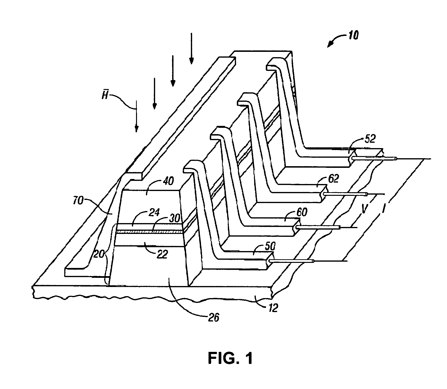
[0035]FIG. 1 is an isometric view of an EMR sensor 10 according to one embodiment. The EMR sensor 10 includes a structure 20 that is a III-V heterostructure formed on a semiconducting substrate 12 such as GaAs. However, the EMR sensor described ...


PUM

PropertyMeasurementUnit
magnetic fieldaaaaaaaaaa
diameteraaaaaaaaaa
widthaaaaaaaaaa

Abstract

A system method and apparatus for determining a position error signal (PES) for servo tracking in a data recording system using a data track. The PES is determined using a sensor array that includes a plurality of sensors offset from one another by certain predetermined distances in a direction perpendicular to the track direction. Correlation functions can be determined for pairs of sensors in the sensor array based on the signals read by the sensors. The results of these correlation functions can then be used to determine a PES by using a look up table or computational processor.

Description

[0001]This is a Continuation In Part Application of commonly assigned U.S. patent application Ser. No. 11 / 069,732 entitled INTEGRATED SERVO AND READ EMR SENSOR, filed on Feb. 28, 2005, which is incorporated herein by reference.FIELD OF THE INVENTION[0002]The present invention relates to magnetoresistive sensors and more particularly to a device employing multiple Extraordinary Magnetoresistive (EMR) sensors for e.g., reading servo and data information from a magnetic medium.BACKGROUND OF THE INVENTION[0003]The heart of a computer's long term memory is an assembly that is referred to as a magnetic disk drive. The magnetic disk drive includes a rotating magnetic disk, write and read heads that are suspended by a suspension arm adjacent to a surface of the rotating magnetic disk and an actuator that swings the suspension arm to place the read and write heads over selected circular tracks on the rotating disk. The read and write heads are directly located on a slider that has an air bea...

Claims


Application Information

Patent Timeline
Patent Type & Authority Patents(United States)
IPC IPC(8): G11B21/02
CPCG11B5/397G11B5/3993G11B5/59655G11B5/3948G11B5/4886
Inventor ALBRECHT, THOMAS ROBERTGURNEY, BRUCE ALVINMARINERO, ERNESTO E.
Owner HITACHI GLOBAL STORAGE TECH NETHERLANDS BV
Why Eureka
Try Eureka