Objective optical system and optical pickup device using it

a technology of optical pickup and optical system, which is applied in the field of objective optical system and optical pickup device using it, can solve the problems of reducing the diffraction efficiency and reducing the stability of tracking, and achieve the effects of improving the diffraction efficiency of light beam, efficient focus, and increasing freedom in selecting the position

Inactive Publication Date: 2009-03-10
FUJI PHOTO OPTICAL CO LTD
View PDF2 Cites 6 Cited by
  • Summary
  • Abstract
  • Description
  • Claims
  • Application Information

AI Technical Summary

Benefits of technology

[0010]The present invention relates to an objective optical system for optical recording media that can efficiently focus each of three light beams on a corresponding one of three optical recording media with different technical standards of the substrate thickness, the wavelengths of the three light beams, and the numerical aperture (NA) of the objective optical system for each of the three light beams. The objective optical system of the present invention uses a diffractive optical element that allows for increased freedom in selecting the position of the objective optical system and improved diffraction efficiency of the light beam with the short wavelength that is used with AODs, along with concurrently increasing the stability of the tracking. The present invention further relates to such an objective optical system with the diffractive optical element being on a lens element of the objective optical system. The present invention further relates to an optical pickup device using this objective optical system.

Problems solved by technology

Additionally, in particular with regard to the light beam with the shortest wavelength of the three light beams, if converging light is incident on the diffractive optical element, there are problems of the diffraction efficiency being reduced due to the angle of incidence of the light rays on the diffractive grooves of the diffractive optical element being tilted from the desired angle of incidence, which greatly decreases the stability of the tracking.

Method used


Image

  • Objective optical system and optical pickup device using it
  • Objective optical system and optical pickup device using it
  • Objective optical system and optical pickup device using it

Examples


embodiment 1

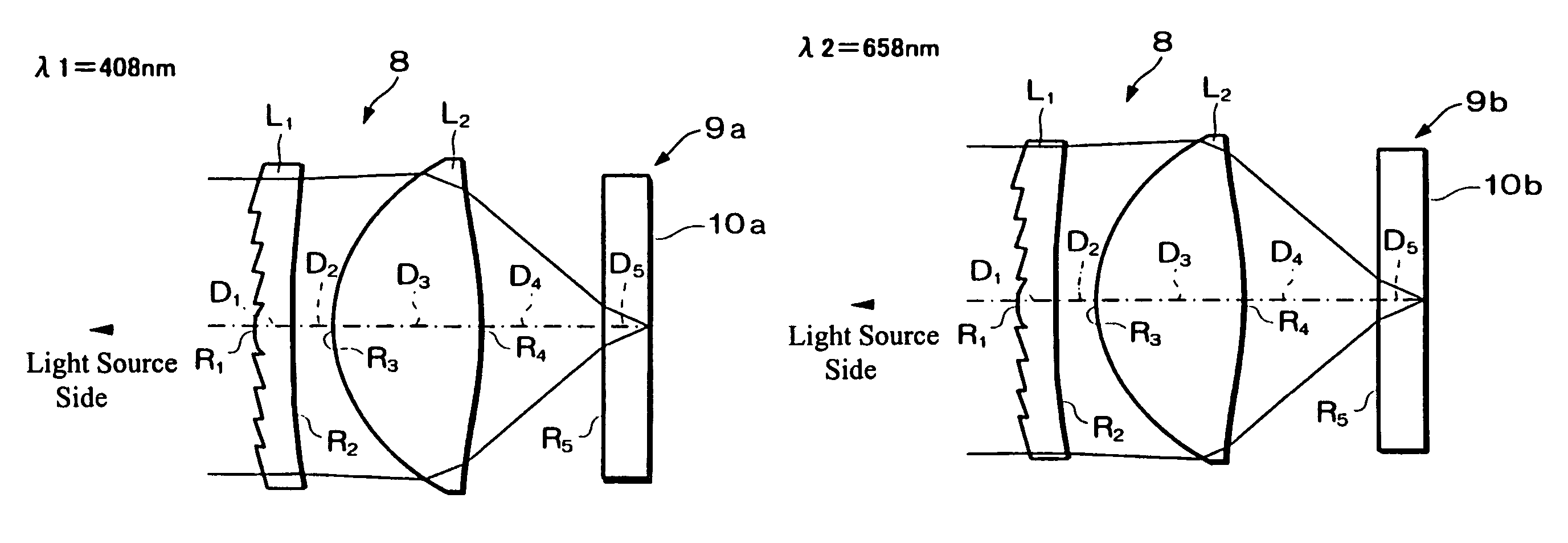
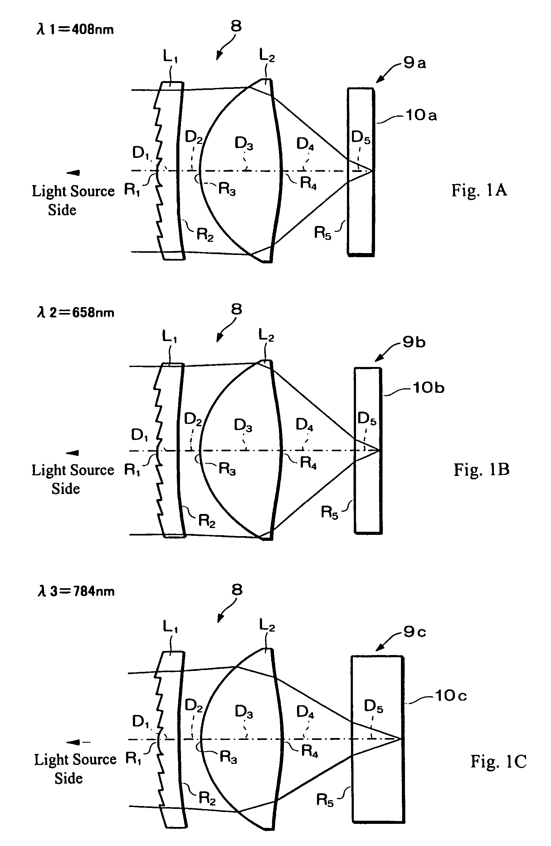
[0064]FIGS. 1A-1C are schematic diagrams that depict cross-sectional views of the objective optical system of Embodiment 1 of the present invention, with FIG. 1A showing the operation of the objective optical system when used with the optical recording medium 9a, with FIG. 1B showing the operation of the objective optical system when used with a second optical recording medium 9b, and with FIG. 1C showing the operation of the objective optical system when used with a third optical recording medium 9c. As shown in FIGS. 1A-1C, the objective optical system of the present invention includes, in order from the light source side, a diffractive optical element L1, with one surface being a diffractive surface and the other surface being a concave spherical surface, and a biconvex objective lens L2 with two rotationally symmetric aspheric surfaces. Additionally, the diffractive surface is formed as a diffractive structure on a virtual plane, that is, the surface where the diffractive struct...

embodiment 2

[0078]Embodiment 2 is very similar to Embodiment 1 and therefore is well shown by FIGS. 1A-1C and FIG. 4. Embodiment 2 differs from Embodiment 1 in its diffractive optical element and objective lens configuration in terms of a different radius of curvature of the concave surface of the diffractive optical element, different values of the constants C, K and the aspheric coefficients of the aspheric surfaces, different spacings between the objective lens and the three optical recording media, and different materials for the diffractive optical element and the objective lens.

[0079]Table 6 below lists the surface #, in order from the light source side, the surface type or radius of curvature (in this case, the radii of curvature are given for planar surfaces, which have a radius of curvature of infinity), the on-axis distance (in mm) between surfaces for the three used wavelengths (λ1=408 nm for the AOD 9a, λ2=658 nm for the DVD 9b, and λ3=784 nm for the CD 9c), and the refractive index...


PUM

PropertyMeasurementUnit
wavelengthaaaaaaaaaa
disk thicknessaaaaaaaaaa

Abstract

An objective optical system is formed of a diffractive optical element with a diffractive surface formed on a virtual plane and an objective lens for focusing three light beams of three different wavelengths at three different numerical apertures onto desired positions of three different recording media with substrates that include different thicknesses, such as an AOD, a DVD, and a CD, that introduce different amounts of spherical aberration in the focused beams. The objective optical system provides compensating spherical aberrations to the three light beams, two of which are incident on the objective optical system as collimated beams and one of which is incident as a diverging beam. The objective optical system focuses second-order diffracted light of one wavelength and first-order diffracted light of the other two wavelengths. An optical pickup device includes the objective optical system, the recording media, and a light source that provides the three light beams.

Description

BACKGROUND OF THE INVENTION[0001]In response to the development of various optical recording media in recent years, an optical pickup device that can be commercially used for recording or reproducing from two types of optical recording media has been known. For example, a device that can record or reproduce either one of a DVD (digital versatile disc) and a CD (compact disc including a CD-ROM, CD-R and CD-RW) using one optical pickup device has been used. For the DVD, it is known to use visible light with a wavelength of, for example, 657 nm, in order to increase the density of the recording. However, there are some CDs that have no sensitivity to visible light, and thus near-infrared light with a wavelength of approximately 790 nm is commonly used.[0002]Therefore, in an optical pickup device that is commonly used for both of these optical recording media, a so-called double wavelength beam system using two beams of different wavelengths may be used to irradiate a recording medium. ...

Claims


Application Information

Patent Timeline
Patent Type & Authority Patents(United States)
IPC IPC(8): G11B7/135G11B7/00G11B7/1353G11B7/1374G11B7/139G11B7/1392
CPCG11B7/1353G11B7/1374G11B7/139G11B7/13922G11B2007/0006
Inventor ORI, TETSUYAKATSUMA, TOSHIAKIMORI, MASAOKITAHARA, YU
Owner FUJI PHOTO OPTICAL CO LTD
Why Eureka
Try Eureka