Laser desorption ion source

a technology of laser pulse and ion source, which is applied in the direction of electron/ion optical arrangement, particle separator tube details, separation process, etc., can solve the problems of inefficient ap-maldi, lack of time-sequenced optics with laser pulse limit ion extraction and transmission efficiency, and lack of efficient atmospheric pressure optics with this device. achieve the effect of increasing the ionization efficiency of a sample and efficient extraction

Active Publication Date: 2006-08-08
PERKINELMER HEALTH SCIENCES INC +1
View PDF6 Cites 31 Cited by
  • Summary
  • Abstract
  • Description
  • Claims
  • Application Information

AI Technical Summary

Benefits of technology

[0018]In accordance with the present invention, associated methods of sample charging, laser desorption and sample ionization are intended to improve the collection efficiency and ionization efficiency of atmospheric pressure, intermediate pressure and vacuum laser desorption ionization.
[0019]Two advantages of the current device should be emphasized. First, precisely timing the sequence of laser pulse with ion extraction under high voltage followed by reduction of the electric field in the extraction and focusing region before losing ions to surfaces. The field in the extraction and focusing region is reduced so that the ions are efficiently focused and transmitted through a conductance aperture into a lower pressure region on the path to a mass analyzer. The second important advantage is the ability to populate the sample surface with ions of the sample polarity as the analyte ions to be extracted. This condition drives the equilibrium toward product with an excess of reagent ions compared to conventional MALDI and increases the efficiency of ionization of analyte. One aspect of the current invention is to precharge a sample prior to laser desorption to enhance the yield of ions from a given sample.
[0021]An object of this invention is to use specialized target surfaces with shaped needles or electrodes behind the sample in order to control the electric field experienced by the sample during and after laser pulse. By varying voltage in space and time, optimum sample precharging, ion generation and extraction of ions can be achieved.
[0023]In accordance with the present invention, atmospheric pressure, intermediate pressure and vacuum laser desorption ion sources comprise ionization chambers and transmission devices encompassing targets for holding samples, lasers to illuminate said targets resulting in desorption and ionization of the samples, time-sequenced electrostatic potentials to foster efficient extraction, focusing, and selecting of resulting gas-phase ions. Laser desorption ion sources in accordance with the invention also comprise a means to accumulate charge on a sample prior to laser desorption of the sample and a means to conduct gas phase ionization of laser desorbed neutral sample molecules to increase the ionization efficiency of a sample during and after a desorption laser pulse.

Problems solved by technology

Ironically, the Franzen and Koster patent begins by arguing that AP-MALDI is inefficient and that augmenting ionization efficiency with gas phase ion-molecule reactions or desorbed neutral species with gas phase reagent ions at atmospheric pressure would offset some of the transmission losses that would occur by inefficient transport from atmospheric pressure.
The lack of efficient atmospheric pressure optics with this device requires precise alignment and positioning of sample and the laser beam relative to the vacuum inlet.
The lack of time-sequenced optics with the laser pulse limit ion extraction and transmission efficiency.
In addition, it is envisioned that mirrored reflective surfaces close to the plume of the MALDI target would tend to become contaminated and degraded in their optical performance.
In addition, the sampling of ions from an electric field between the target and aperture into the field-free region of the vacuum inlet tube would cause rim losses from field penetration and degrade the transport efficiency.
The lack of time-sequenced optics with the laser pulse limit ion extraction and transmission efficiency.
This device is still subordinate to alignment of laser, target, and lacks spatial or temporal optics to facilitate efficient ion transmission to the mass analyzer.

Method used


Image

  • Laser desorption ion source
  • Laser desorption ion source
  • Laser desorption ion source

Examples


Embodiment Construction

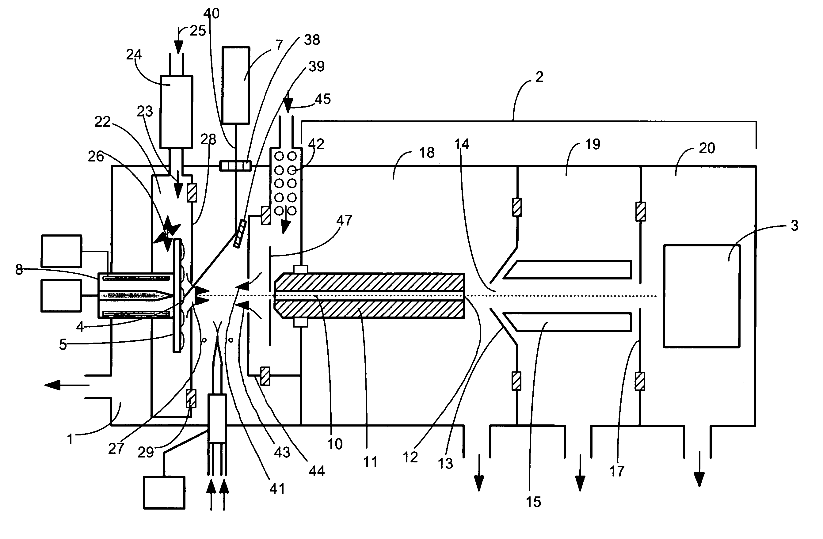
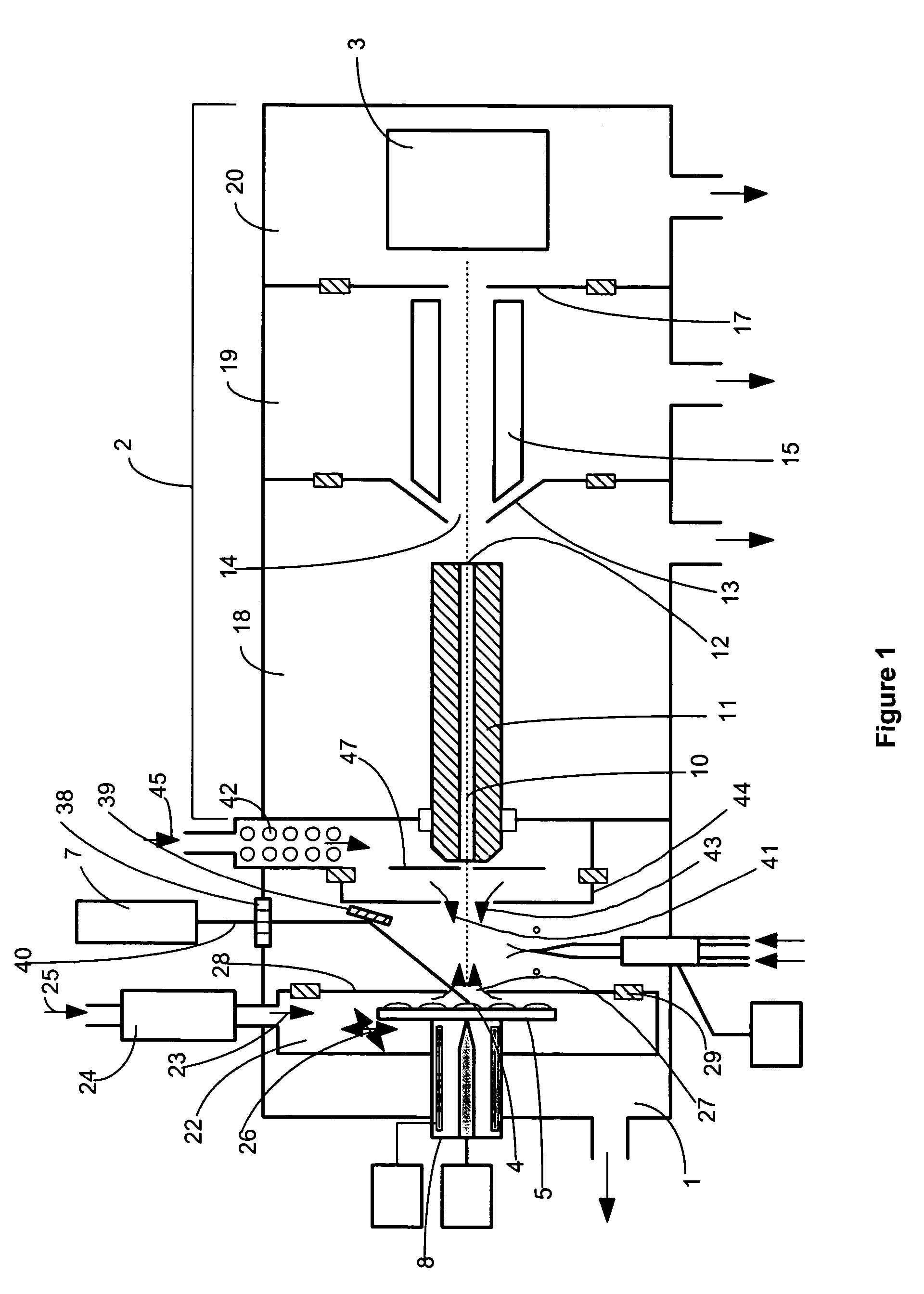
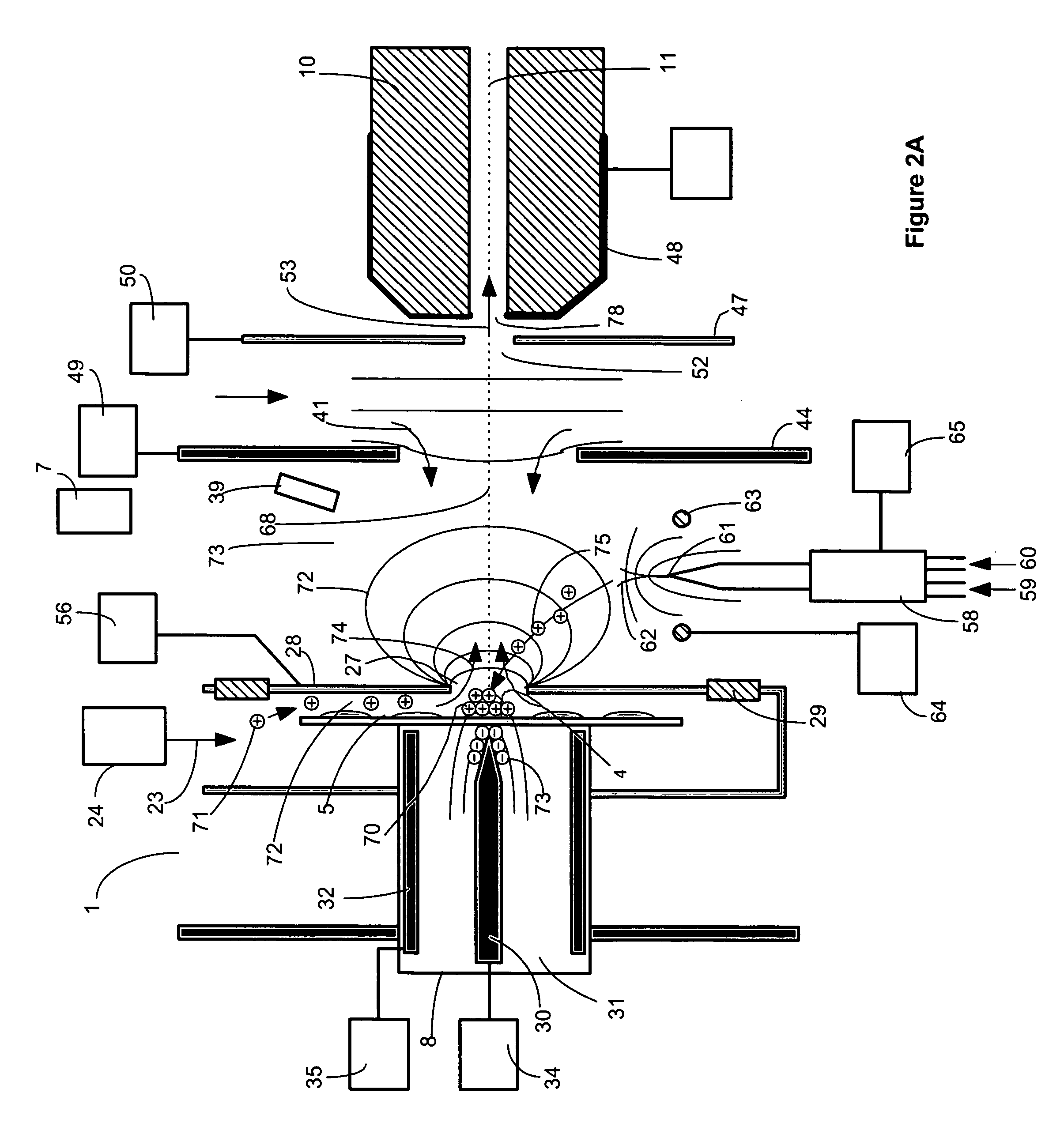
[0050]A preferred embodiment of the invention comprising an atmospheric pressure Laser Desorption Ionization source with sample surface charging is diagrammed in FIG. 1. Operating details for Laser Desorption Ionization source 1 are diagrammed in FIGS. 2A through 2D. Laser Desorption Ionization (LDI) source 1 interfaced to vacuum system 2 comprising ion transfer optics and mass to charge analyzer with detector 3, produces ions from sample 4 on target plate 5. A portion of the laser desorption ion population produced is focused into bore 10 of capillary 11. Ions exit capillary bore 10 at capillary exit end 12 into vacuum and are accelerated in a free jet expansion of neutral background gas flowing through capillary bore 10 from atmospheric pressure ion source 1. Capillary 11 may comprise a dielectric capillary with conductive electrodes on the entrance and exit faces, a heated electrically conductive capillary, a nozzle, an orifice or an array of orifices into vacuum. Ions pass throu...


PUM


Abstract

Atmospheric pressure, intermediate pressure and vacuum laser desorption ionization methods and ion sources are configured to increase ionization efficiency and the efficiency of transmitting ions to a mass to charge analyzer or ion mobility analyzer. An electric field is applied in the region of a sample target to accumulate ions generated from a local ion source on a solid or liquid phase sample prior to applying a laser desorption pulse. The electric field is changed just prior to or during the desorption laser pulse to promote the desorption of charged species and improve the ionization efficiency of desorbed sample species. After a delay, the electric field may be further changed to optimize focusing and transmission of ions into a mass spectrometer or ion mobility analyzer. Charged species may also be added to the region of the laser desorbed sample plume to promote ion-molecule reactions between the added ions and desorbed neutral sample species, increasing desorbed sample ionization efficiency and / or creating desired product ion species. The cycling of electric field changes is repeated in a timed sequence with one or more desorption laser pulse occurring per electric field change cycle. Embodiments of the invention comprise atmospheric pressure, intermediate pressure and vacuum pressure laser desorption ionization source methods and devices for increasing the analytical flexibility and improving the sensitivity of mass spectrometric analysis.

Description

CROSS-REFERENCE TO RELATED APPLICATIONS[0001]This application is entitled to the benefits of Provisional Patent Application Ser. No. 60 / 476,576 filed Jun. 7, 2003; Provisional Patent Applications Ser. No. 60 / 210,877 filed Jun. 9, 2000, now U.S. Pat. No. 6,744,041 B2 issued Jun. 1, 2004; Provisional Patent Application Ser. No. 60 / 293,648, filed 2001, May 26, now patent application Ser. No. 10 / 155,151 filed 2002, May 25; Provisional Patent Application Ser. No. 60 / 384,869, filed 2002, Jun. 1, now patent application Ser. No. 10 / 499,147, filed 2003, May 31; Provisional Patent Application Ser. No. 60 / 384,864, filed 2002, Jun. 1, now patent application Ser. No., 10 / 499,344, filed 2003, May 30; Provisional Patent Application Ser. No. 60 / 410,653, filed 2002, Sep. 13, now patent application Ser. No. 10 / 661,842, filed 2003, Sep. 12; Provisional Patent Application Ser. No. 60 / 419,699, filed 2002, Oct. 18, now patent application Ser. No. 10 / 688,021, filed 2003, Oct. 17; and Provisional Patent Ap...

Claims


Application Information

Patent Timeline
Patent Type & Authority Patents(United States)
IPC IPC(8): H01J49/04H01J49/10H01J49/40H01J49/00
CPCH01J49/164H01J49/06
Inventor WILLOUGHBY, ROSS C.SHEEHAN, EDWARD W.WHITEHOUSE, CRAIG M.
Owner PERKINELMER HEALTH SCIENCES INC
Why Eureka
Try Eureka