Sensor

Inactive Publication Date: 2009-03-17
CONTINENTAL AUTOMOTIVE GMBH
View PDF19 Cites 5 Cited by
  • Summary
  • Abstract
  • Description
  • Claims
  • Application Information

AI Technical Summary

Benefits of technology

[0003]The object of the invention is therefore to provide a sensor of the type mentioned in the introduction which can be produced and installed in a particularly cost-effective manner, but at the same time ensures that its connector and the electrical line leading to said connector are effectively protected until the sensor is installed at the location of its final intended position.
[0005]In one refinement of the invention, predetermined breaking points are formed on the retaining bridge and are destroyed when the sensor is installed at the location of its final intended position. The predetermined breaking points on the retaining bridge make it possible for said retaining bridge to be deliberately separated after the sensor is installed at the location of its final intended position. The retaining bridge then breaks off at previously precisely determined points, as a result of which the incorporated sensor is prevented from being damaged by the retaining bridge being separated.
[0007]Installation time and costs are saved as a result of the inventive method for installing a sensor on a wheel bearing of a motor vehicle. It is only necessary to press the sensor onto a wheel bearing, to remove the connector from the retaining bridge and connect it to the downstream electronics, and then push away the retaining bridge using the vehicle axle. This considerably reduces the number of method steps required to install the sensor at the location of its final intended position.

Problems solved by technology

Up until the sensor is installed at the location of its final intended position, that is to say on the wheel bearing of a motor vehicle for example, the connector has to be mounted in such a way that neither it nor the electrical line leading to it are damaged in any way.
This method of securing the connector to the sensor before said sensor is installed at the location of its final intended position is very complicated and expensive.
Removal of the transportation ring from the sensor when said sensor is installed generates additional expenditure and the material of the transportation ring is lost.

Method used


Image

  • Sensor
  • Sensor
  • Sensor

Examples


Embodiment Construction

)

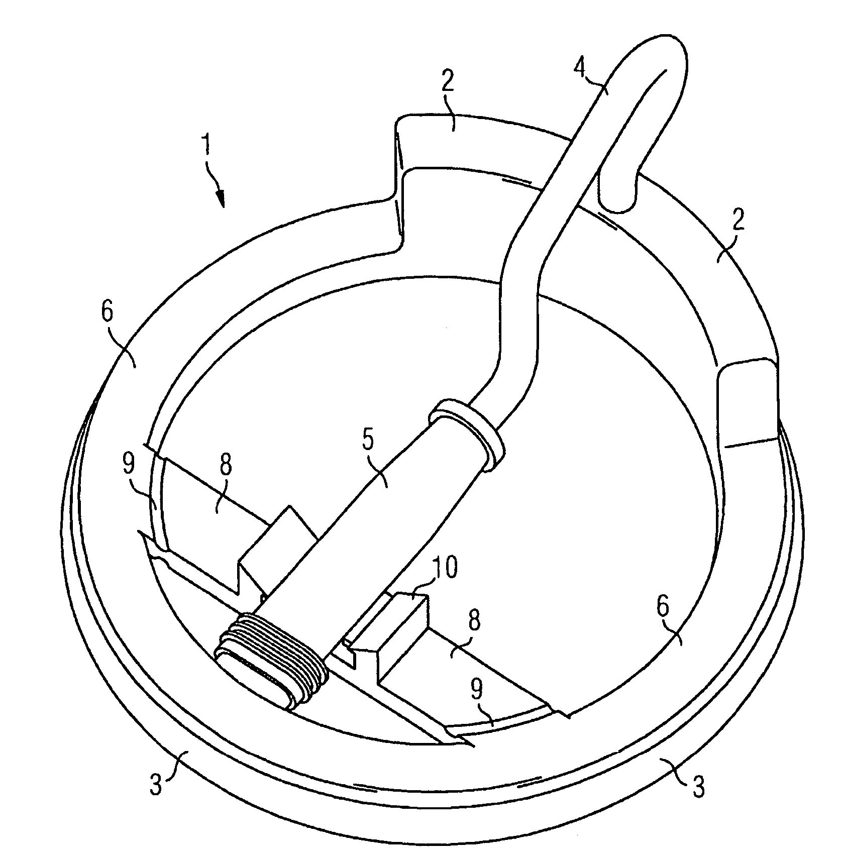
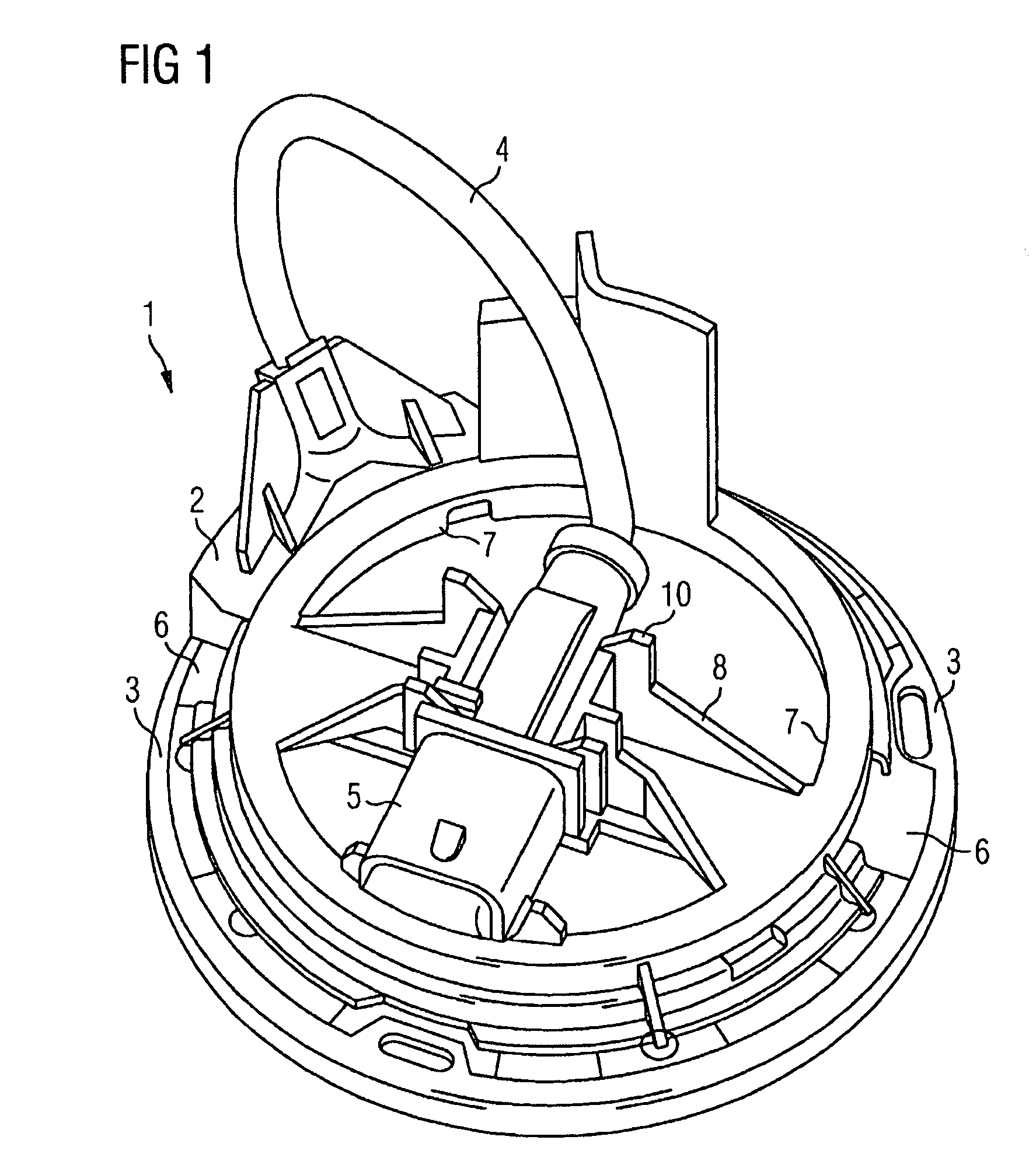
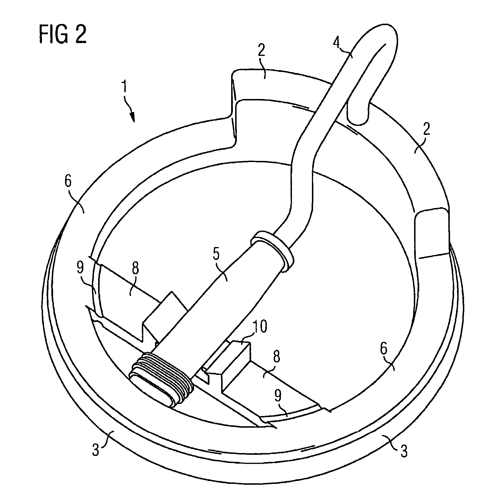
[0013]FIG. 1 shows a perspective view of a sensor 1 with a transportation ring 7 according to the prior art. The sensor 1 comprises a sensor block 2, a securing ring 3, an electrical line 4, a connector 5 and an extrusion coating 6. The sensor block 2 contains the electronics required to detect a signal. For example, the sensor block 2 may contain a Hall element which can detect the variation in a magnetic field, as a result of which the sensor 1 is able to detect the rotational speed of a wheel of a motor vehicle, for example.

[0014]The sensor block 2 is connected to the securing ring 3. The extrusion coating 6 is applied both to the securing ring 3 and to the sensor block 2 in an injection-molding process. There may also be further mechanical connections (not illustrated here) between the sensor block 2 and the securing ring 3. The electronic signals generated by the sensor block 2 are fed to the connector 5 via the electrical line 4. The connector 5 is connected to downstream ele...


PUM


Abstract

A sensor, suitable for being secured to a wheel bearing of a motor vehicle and serving to measure the rotational speed of the wheel, has a securing ring, a sensor block, at least one electrical line, at least one connector and at least one retaining bridge. The sensor block is electrically connected to the connector by means of the electrical line, and is connected to the securing ring at least by means of a plastic extrusion coating. A retaining bridge is integrally formed on the plastic extrusion coating and carries the connector until the sensor is installed at the location of its final intended position.

Description

FIELD AND BACKGROUND OF THE INVENTION[0001]The invention relates to a sensor, in particular to a sensor which is secured to a wheel bearing of a motor vehicle and serves to measure the rotational speed, having a securing ring, a sensor block, at least one electrical line, at least one connector and at least one retaining bridge, with the sensor block being electrically connected to the connector by means of the electrical line, and the sensor block being connected to the securing ring at least by means of a plastic extrusion coating.[0002]Sensors of the type mentioned in the introduction are used, for example, in motor vehicles for detecting the rotational speed of a wheel. Up until the sensor is installed at the location of its final intended position, that is to say on the wheel bearing of a motor vehicle for example, the connector has to be mounted in such a way that neither it nor the electrical line leading to it are damaged in any way. To this end, a transportation ring which ...

Claims


Application Information

Patent Timeline
IPC IPC(8): G01P1/02G01D11/20G01D11/24G01D11/30G01P3/44
CPCG01D11/245G01D11/30G01P1/026G01P3/443
Inventor MACHILL, ANDREAS
Owner CONTINENTAL AUTOMOTIVE GMBH
Why Eureka
Try Eureka