Conduit junction box adapter closure

a technology for connecting cables and conduits, which is applied in the direction of electrical apparatus casings/cabinets/drawers, coupling device connections, installation of lighting conductors, etc., can solve the problems of inability to adapt, difficult and costly repairs, and lateral support will be omitted, so as to prolong the life of screws, reduce and increase the number of coupling hubs. the effect of location

Inactive Publication Date: 2009-03-17
LAMMENS JR ALBERT JAMES +1
View PDF3 Cites 23 Cited by
  • Summary
  • Abstract
  • Description
  • Claims
  • Application Information

AI Technical Summary

Benefits of technology

[0007]One embodiment of the present invention provides an efficient and cost-effective means of adding one or perhaps two coupling hubs at different locations or orientations or another type of electrical pass-through interface to an existing junction box of the design disclosed in my U.S. Pat. No. Re 35,075. A structure which includes an adapter closure plate can be installed on my new in-service conduit boxes. The result is an increase in the number, location, and orientation of the coupling hubs on an in-service conduit body. The adapter closure is designed so that the conduit body will provide shear support to the adapter plate. This is achieved by shaping the adapter cover to achieve a tight, recessed fit within the female opening of the conduit body. Providing this form of lateral support will prolong the life of the screws by reducing the resultant shear force on the screws from lateral loading and prevent screw failure that could result from excessive shear strain and / or stress enhanced corrosion. Providing this lateral support will obviate difficult and costly repairs to the conduit box that could result from the shear failure of the screws. Lateral loading could be the result of either misalignment between the coupling hub and the electrical conduit, or a result of lateral forces applied to the electrical conduit and transferred to the adapter closure through the coupling hub.
[0008]To further enhance lateral support against shear forces, and to rigidify the adapter cover against bending and / or torsional forces, it is contemplated to form the cover plate so that the underside is slightly concave seen as arcuate in cross-section. As will be more specifically described hereinafter, this arcuate configuration of the cover plate in cooperation with the recessed fitment of the plate within the female opening of the body significantly increases resistance to shear forces.
[0012]For such instances, an alternative embodiment of the present invention provides structure for gaining more interior space for an in-service conduit box; and has the option for also adding more additional conduits to an in-service conduit installation. Disclosed herein are new structures for attaching two of my extension boxes together by joining the female sides together. This provides an alternative way of providing additional conduits to an in-service conduit body, and also for increasing interior working space when needed. This embodiment has the added advantage that more than two new conduits may be added depending upon which hub configuration series is selected for the added body.
[0017]It is a further object of the present invention to provide structure for joining conduit boxes together in order to provide additional conduits to an in-service assembly and to also add additional interior working space.

Problems solved by technology

Providing this lateral support will obviate difficult and costly repairs to the conduit box that could result from the shear failure of the screws.
Because my new conduit bodies have a front and a rear opening, they are not adaptable to the LB series bodies which include a hub configuration for the body bottom.

Method used


Image

  • Conduit junction box adapter closure
  • Conduit junction box adapter closure
  • Conduit junction box adapter closure

Examples


Embodiment Construction

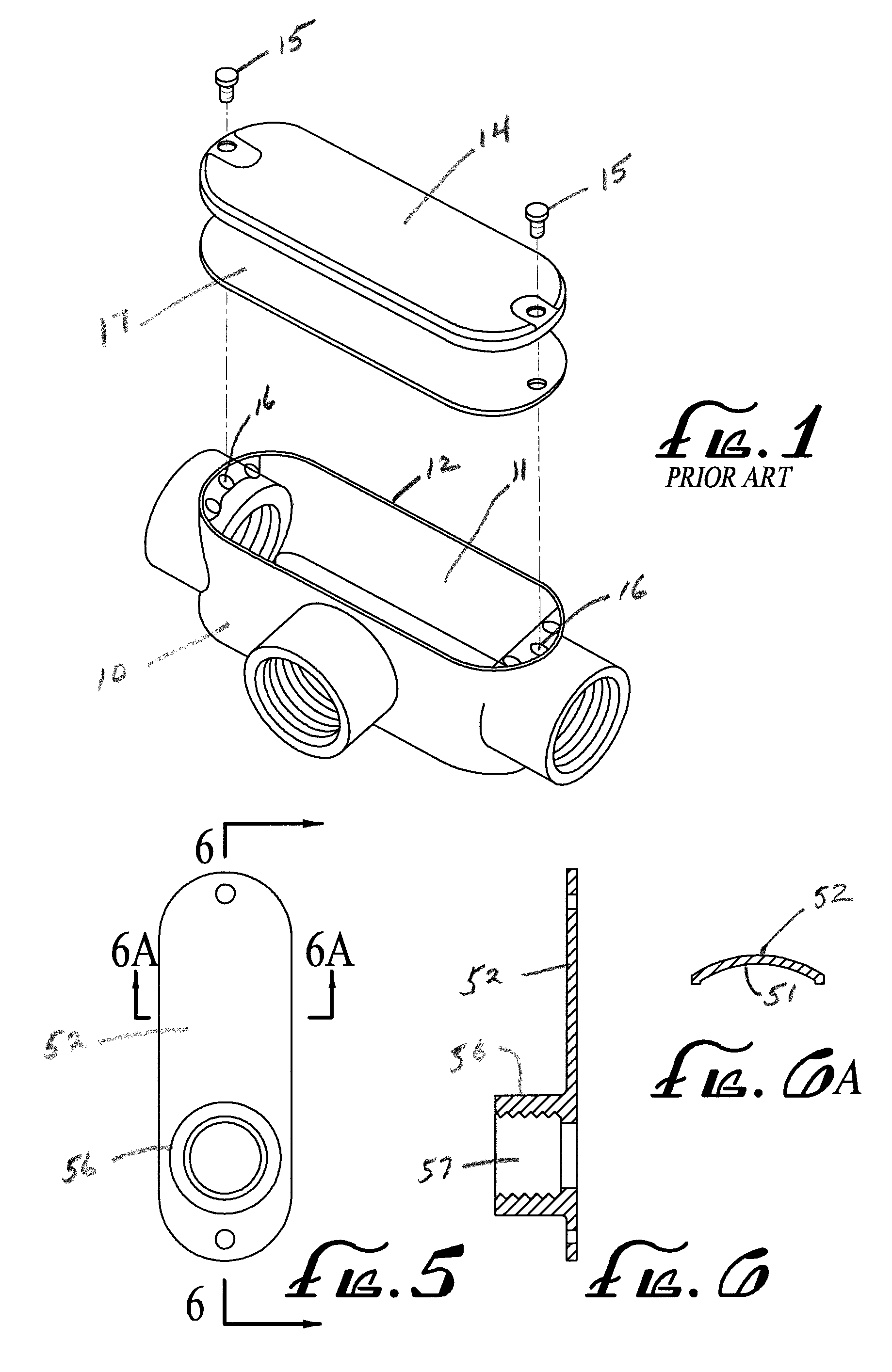
[0030]Referring now in detail to the drawings, FIG. 1 is an illustration of a prior art conduit box. The assembly shown in FIG. 1 comprises a NEC “T” type box 10 with a hollow interior 11 and having an opening 12 through which the hollow interior is accessible. This conventional type box is closed with a flat cover plate 14, which is secured to body 10 by removable threaded fasteners 15, which are received in threaded apertures 16 in the body 10. The removable cover 14 seals the interior 11 of the box by means of gasket 17 placed intermediate the cover 14 and the rim 12.

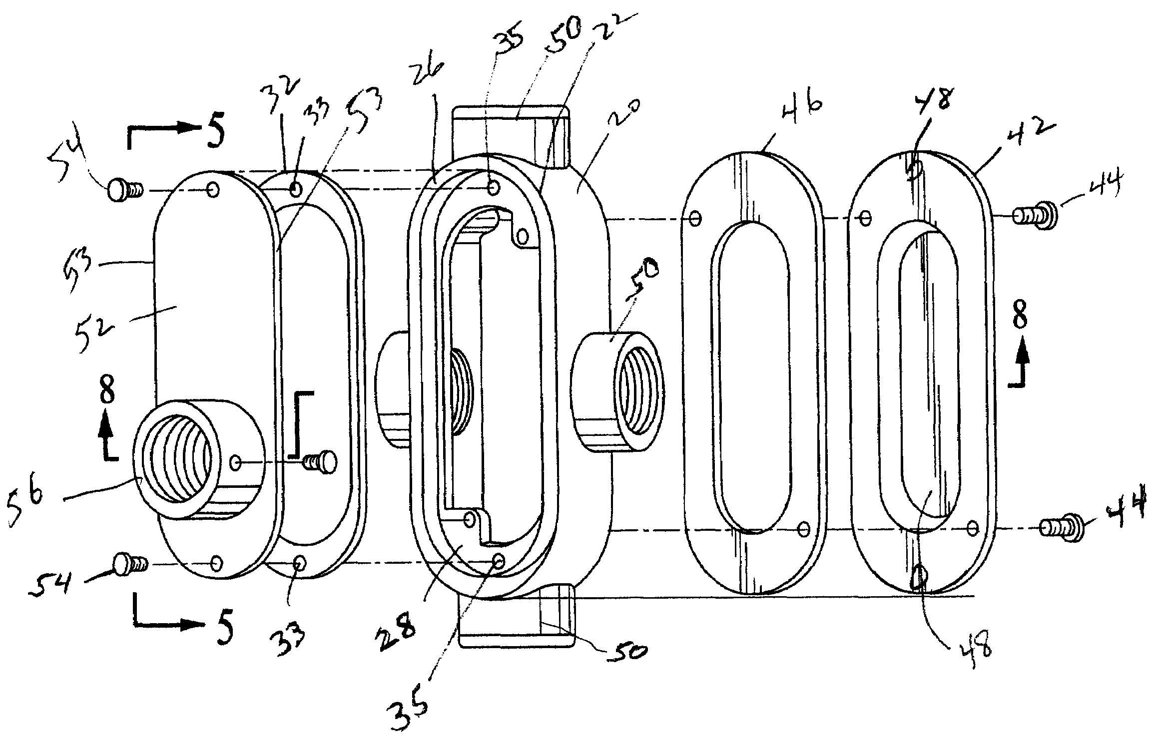
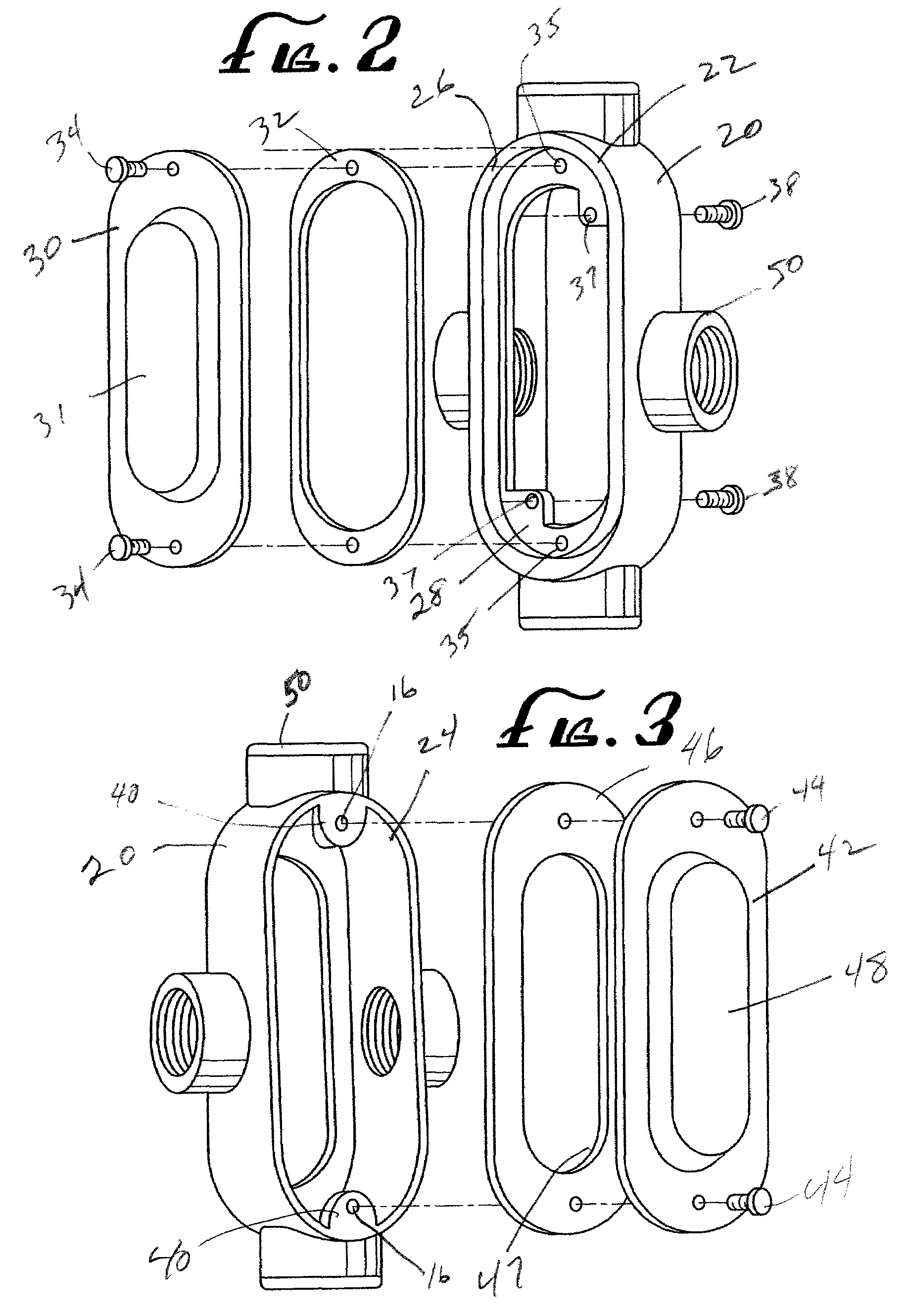
[0031]FIGS. 2 and 3 illustrate a modified form of conduit junction box comparable to that shown in FIGS. 1 and 2 of my U.S. Pat. No. RE 35,075. In contrast to the utilization of my new conduit body as an extension box as disclosed in U.S. Pat. No. RE 35,075, FIGS. 2 and 3 of the present invention demonstrate the use of my conduit junction body in an in-service installation or, in other words, as the primary junction ...


PUM


Abstract

An adapter closure structure for electrical conduit systems of the type having conduit bodies, for which additional conduit access to an in-service conduit junction box can be provided without the need for removing and / or rewiring the in-service junction box. In a first embodiment, a structure is provided in the form of a closure plate having one or more conduit hubs to replace a flat closure plate on one side of a conduit body. In a second embodiment, a second conduit body may be joined to the in-service body utilizing a novel coupling ring. In this alternative embodiment, the second body can provide additional interior working space. In addition the second body may also optionally add one or several additional conduit hubs for added access to the in-service system. In both embodiments, the closure structure is fitted into a female opening of the conduit body for structural integrity.

Description

CROSS-REFERENCE TO RELATED APPLICATIONS[0001]This application is a continuation-in-part of pending U.S. patent application Ser. No. 11 / 368,082, which is a CIP of U.S. patent application Ser. No. 11 / 156,260, filed Jun. 17, 2005; which itself claims the benefit of U.S. Provisional Patent Application Ser. No. 60 / 581,963, filed Jun. 22, 2004.BACKGROUND OF THE INVENTION[0002]The field of the invention is electrical junction boxes and conduit junction boxes. Conduit junction boxes are a type of electrical junction box. Most building codes require most electrical wiring to be enclosed in conduits which are coupled to one another at junction boxes. A typical junction box has a hollow body with at least one open side. A junction box may have threaded or non-threaded coupling hubs extending through the walls of the box and an interior space that is accessible through an open side of the box. The coupling hubs provide the point of connection between the conduit and the junction box. Electric c...

Claims


Application Information

Patent Timeline
Patent Type & Authority Patents(United States)
IPC IPC(8): H02G3/08
CPCH02G3/086H02G3/14
Inventor LAMMENS, JR., ALBERT JAMESMARX, RANDY LAMAR
Owner LAMMENS JR ALBERT JAMES
Why Eureka
Try Eureka