Electrode structures, display devices containing the same

a technology of electrode structure and display device, which is applied in the manufacture of electrode systems, electric discharge tubes/lamps, discharge tubes luminescnet screens, etc., can solve the problems of shortening of focusing electrode and grid electrode, and achieve the effect of reducing shortening between the two electrodes and increasing the yield of display devices containing such an electrode structur

Inactive Publication Date: 2009-03-17
MICRON TECH INC
View PDF22 Cites 2 Cited by
  • Summary
  • Abstract
  • Description
  • Claims
  • Application Information

AI Technical Summary

Benefits of technology

[0011]The present invention provides the following advantages over the prior art. By providing an electrode structure with an insulating ridge disposed between the gate and focusing electrodes, shorting between the two electrodes is reduced. Thus, the yield enhancement of display devices containing such an electrode structure is increased.

Problems solved by technology

A problem with both types of focusing electrodes is the close proximity of the focusing electrode with the gate electrode (also known as the extraction grid).
When the focusing electrode is close to the gate electrode, small particles can cause the grid electrode and focusing electrode to short and cause failure.

Method used


Image

  • Electrode structures, display devices containing the same
  • Electrode structures, display devices containing the same
  • Electrode structures, display devices containing the same

Examples


Embodiment Construction

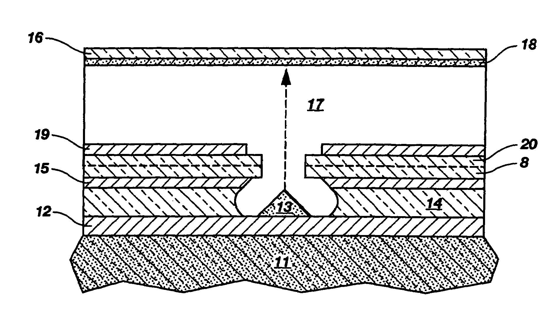
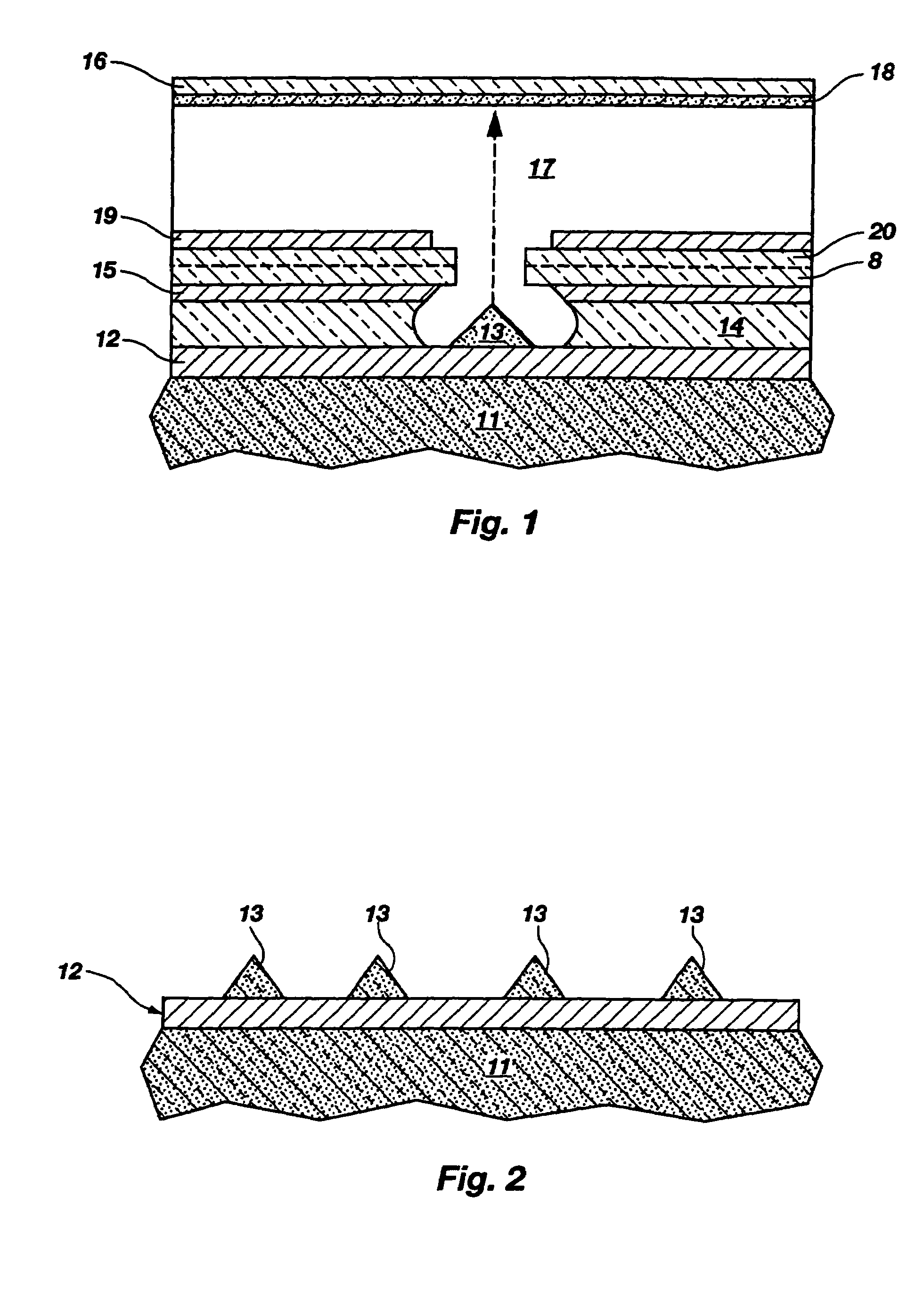
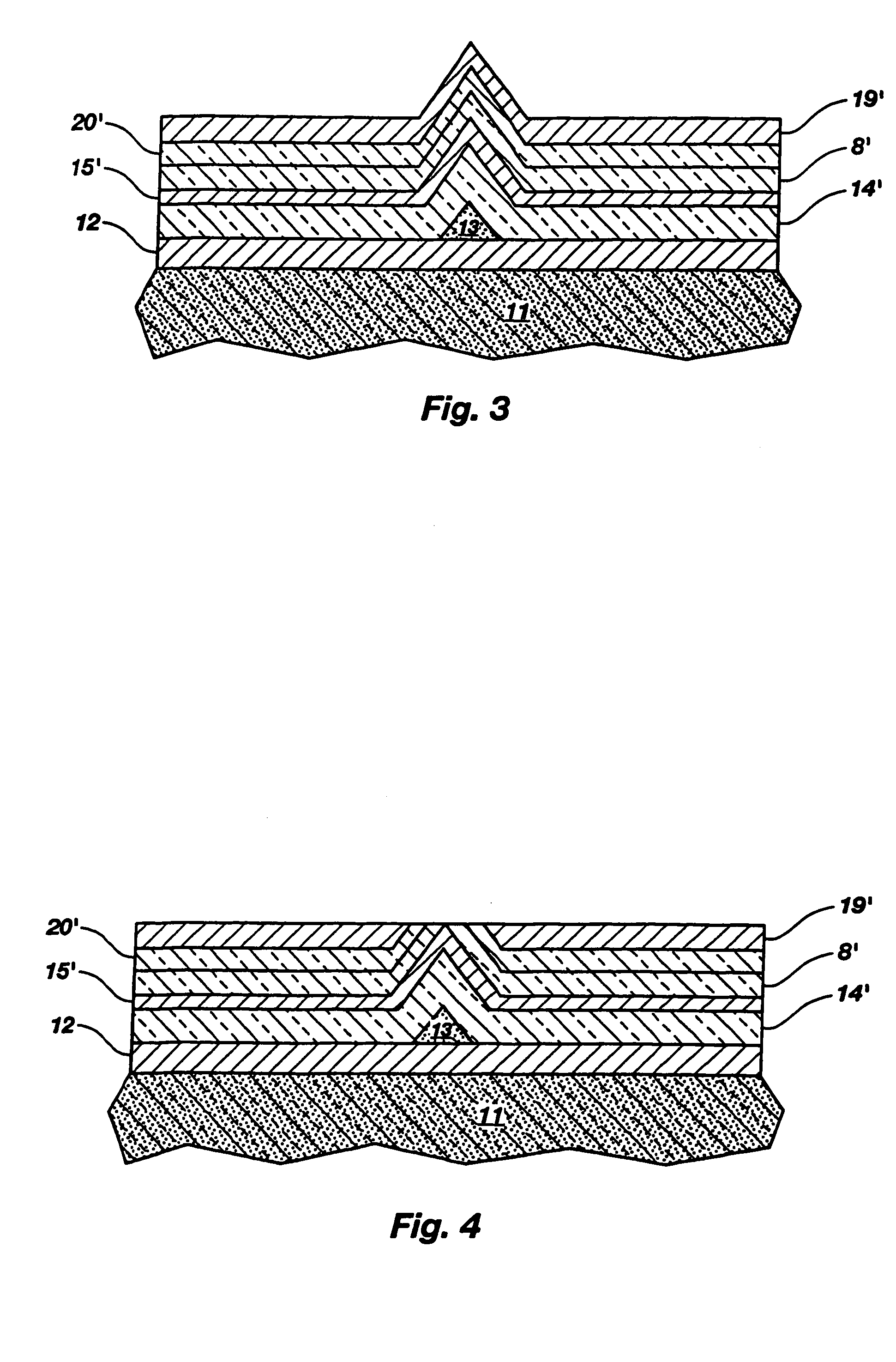
[0027]The present invention provides a method and structure for separating the focusing and gate electrodes of a display device by an insulating region or ridge between the two electrodes. The insulating region or ridge is formed of materials which electrically insulate the focusing electrode and gate electrode, thereby reducing shorting between these two layers.

[0028]The following description provides specific details, such as material thicknesses and types, in order to provide a thorough understanding of the present invention. The skilled artisan, however, will understand that the present invention may be practiced without employing these specific details. Indeed, the present invention can be practiced with conventional fabrication techniques employed in the industry.

[0029]The process steps and structures described below neither form a complete process flow for manufacturing display devices nor a completed device. Only the process steps and structures necessary to understand the p...


PUM


Abstract

An electrode structure for a display device comprising a gate electrode proximate to an emitter and a focusing electrode separated from the gate electrode by an insulating layer containing a ridge are provided. When the focusing electrode is an aperture-type electrode, the ridge protrudes closer to the emitter than the sidewall of the gate electrode or the sidewall of the focusing electrode. When the focusing electrode is a concentric-type electrode, the ridge protrudes above the upper surface of the gate electrode or the upper surface of the focusing electrode. A method for making the aperture-type and concentric-type electrode structures is described. A display device containing such electrode structures is also described. By forming an insulating ridge between the gate and focusing electrodes, shorting between the two electrodes is reduced and yield enhancement increased.

Description

CROSS-REFERENCE TO RELATED APPLICATIONS[0001]This application is a continuation of application Ser. No. 10 / 634,075, filed Aug. 4, 2003, now U.S. Pat. No. 6,900,586, issued May 31, 2005, which is a continuation of application Ser. No. 09 / 885,624, filed Jun. 20, 2001, now U.S. Pat. No. 6,630,781, issued Oct. 7, 2003, which is a continuation of application Ser. No. 09 / 576,018, filed May 23, 2000, now U.S. Pat. No. 6,259,199, issued Jul. 10, 2001, which is a divisional of application Ser. No. 09 / 102,223, filed Jun. 22, 1998, now U.S. Pat. No. 6,224,447, issued May 1, 2001.GOVERNMENT RIGHTS[0002]This invention was made with United States Government support under contract No. DABT 63-93-C-0025 awarded by the Advanced Research Projects Agency (ARPA). The United States Government has certain rights in this invention.BACKGROUND OF THE INVENTION[0003]This invention relates to display devices, such as field emission displays, plasma displays, and flat panel cathode ray tubes. Specifically, the...

Claims


Application Information

Patent Timeline
Patent Type & Authority Patents(United States)
IPC IPC(8): H01J1/02H01J1/30H01J1/304H01J3/02
CPCH01J3/022H01J2329/00
Inventor MORADI, BENHAMXIA, ZHONG-YIZHANG, TIANHONG
Owner MICRON TECH INC
Why Eureka
Try Eureka