Cement slurry collection chute basin

a technology of cement slurry and chute basin, which is applied in the direction of liquid handling, cleaning using liquids, packaged goods types, etc., can solve the problems of unreliable existing systems, unusable, and difficult rolling a heavy container across, so as to eliminate any spillage, facilitate the discharge, and facilitate the movement

Inactive Publication Date: 2009-03-24
MANNO JOSEPH J
View PDF11 Cites 24 Cited by
  • Summary
  • Abstract
  • Description
  • Claims
  • Application Information

AI Technical Summary

Benefits of technology

[0020]The principal advantage of the cement slurry collection chute basin is to keep from discarding concrete slurry randomly at construction sites.

Problems solved by technology

For example, it may be desirable to prevent or limit the runoff of the cement slurry and aggregates onto the ground, as the run-off materials may constitute a serious environmental hazard.
Further, the run-off materials may constitute lost resources to the concrete provider.
However, existing systems are unreliable and are not user-friendly.
This indicates the need for such an apparatus, but does not address the feet that most of the areas that concrete is delivered is on rough, uneven dirt surfaces where rolling a heavy container across would not be easy, if not impossible.
This apparatus would also involve a major adaptation to all the delivery trucks that would not be practical.
These devices are generally difficult to keep watertight and allow some of the water and concrete slurry to leak out which is now becoming more of an environmental problem than it has been in the past and can be a hazard on the highways.
This patent describes a complete system presently in use on many concrete trucks, but the removable container attached to the end of the concrete chute is difficult to use due to the attachment means, and it does not provide a spill proof means of cleaning the chute.
This patent tells of another complete system presently in use on many concrete trucks, but the removable container attached to the end of the concrete chute is also difficult to use due to the attachment means, and it does not provide a spill proof means of cleaning the chute.

Method used


Image

  • Cement slurry collection chute basin
  • Cement slurry collection chute basin
  • Cement slurry collection chute basin

Examples


Embodiment Construction

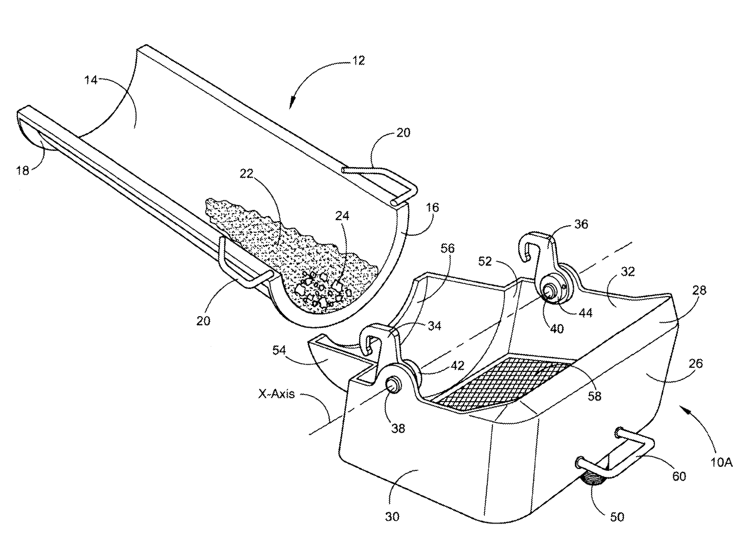
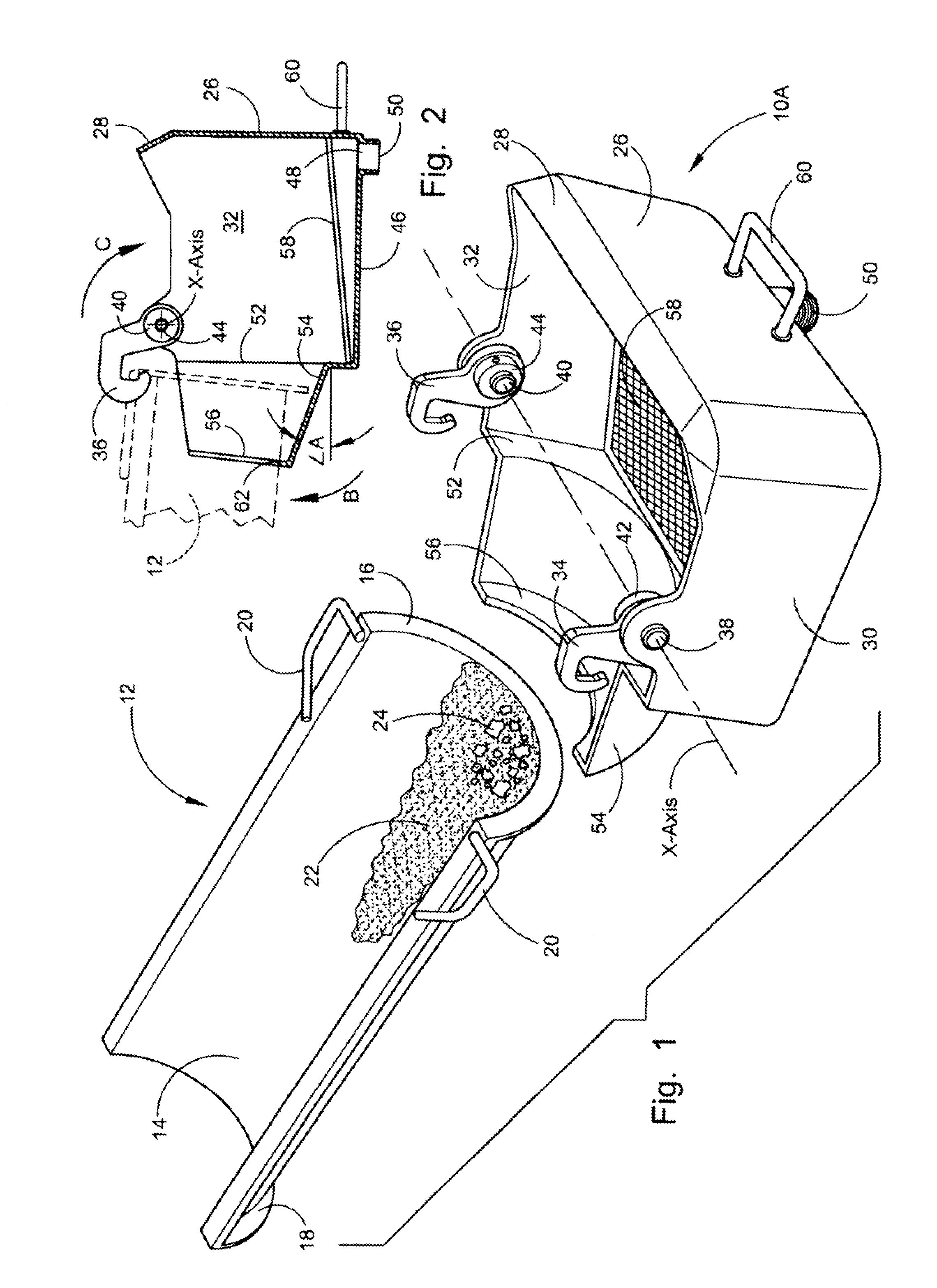
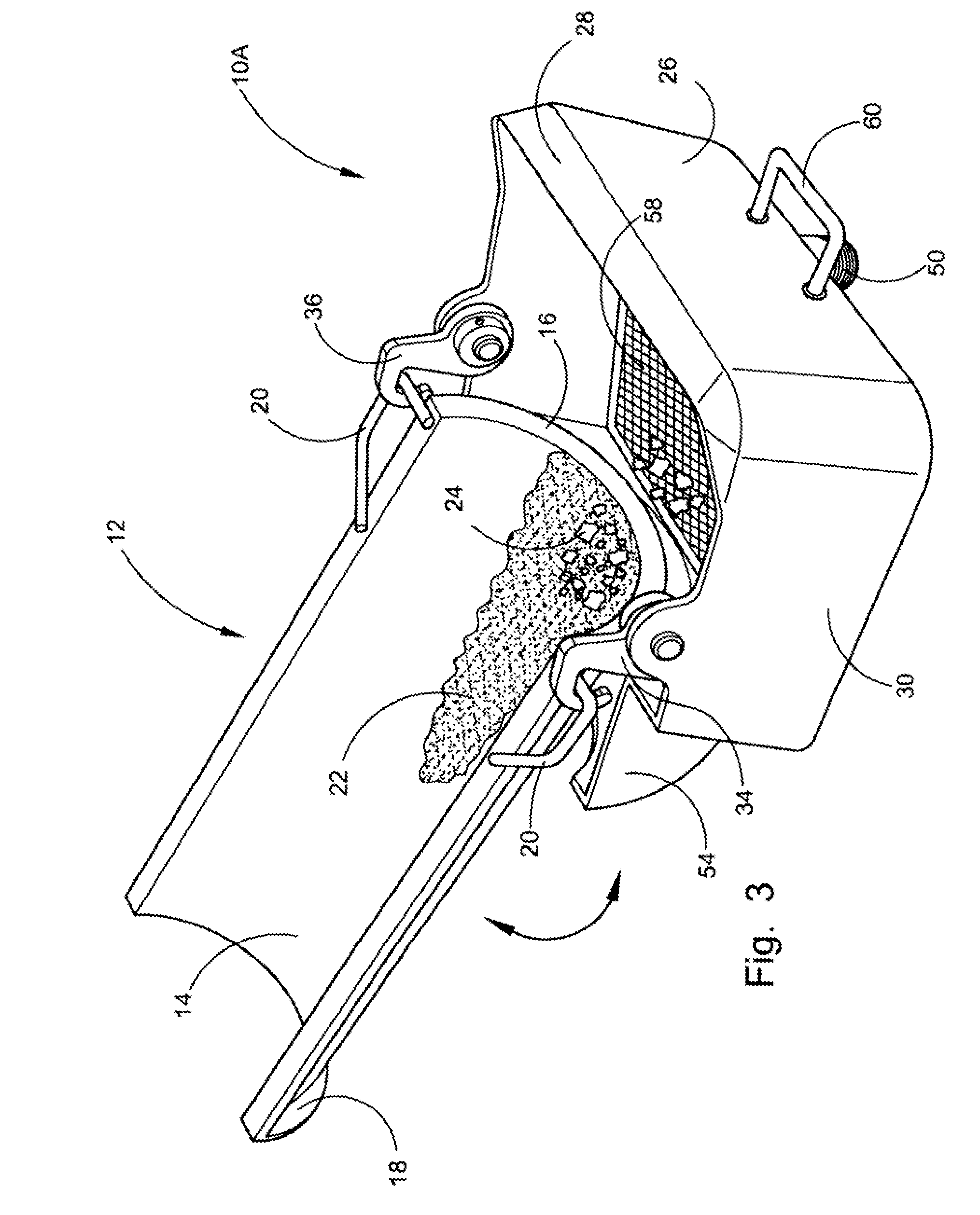
[0043]Referring now to the drawings, wherein similar parts of the preferred embodiment of the cement slurry collection chute basin 10A and the alternate embodiment of the cement slurry collection chute basin 10B are identified by like reference numerals. There is seen in FIG. 1 an exploded perspective view of the cement slurry collection chute basin 10A adjacent to a conventional concrete flop chute 12 attached to a concrete delivery truck. Concrete flop chutes 12 consist of a curved trough 14 with mating flanges 16 and 18 at each end. Two handles 20 are used to carry the chutes, and to attach to additional chutes when lengthening the dispensing capability. After the delivery has been completed, the concrete flop chutes 12 have a residue of a wet cement mixture referred to as cement slurry 22 and small gravel called aggregate 24. This aggregate 24 will be separated from the slurry 22 by a screen 58. The cement slurry 22 will continue through the screen 58 without the aggregate 24 to...


PUM

PropertyMeasurementUnit
angleaaaaaaaaaa
angleaaaaaaaaaa
slant angleaaaaaaaaaa

Abstract

The present application is directed at a cement slurry collection chute basin that incorporates a leak proof means, no matter what the size or condition of the end of the concrete flop chute. By using a forward angled entry trough with a square large basin area having the attachment hooks in a forward position, the weight is put in the rear and the forward edge of the device is held forward of the end flange and tight against the lower surface of the concrete chute. A screen separates the aggregate from the cement slurry, which flows out a drain orifice in the bottom. An alternate embodiment is constructed from “half-pipe” housing. This alternate embodiment cement slurry collection chute basin will be much more efficient and economical to manufacture because of the “half-pipe” construction and the ease with which it could he welded and fabricated into form.

Description

[0001]This U.S. patent application claims the benefit of, and is a Continuation-In-Part (CIP) of U.S. patent application Ser. No. 10 / 537,140 filed on Jun. 1, 2005, which claims the benefit of PCT patent application serial no. PCT / US05 / 08736 filed on Mar. 16, 2005, which in turn claims the benefit of U.S. provisional patent application Ser. No. 60 / 638,325 filed on Dec. 21, 2004.FIELD OF THE INVENTION[0002]This application relates in general to an apparatus and method for the collection of cement slurry and aggregates from a concrete mixing truck at a construction site. In particular, the present invention deals with the recovery of cement slurry and aggregates exiting in the flop chutes and other equipment used in the delivery of the cement to the construction site, by providing a leak-proof cement slurry collection chute basin.BACKGROUND OF THE INVENTION[0003]Concrete is frequently delivered to a construction site in a concrete mixer truck. The truck may have a rotating drum in whic...

Claims


Application Information

Patent Timeline
Patent Type & Authority Patents(United States)
IPC IPC(8): B65B1/04B08B3/04
CPCB03B9/063B07B1/04B08B9/00B28C5/4203B28C7/16Y02W30/58Y02W30/52
Inventor MANNO, JOSEPH J.
Owner MANNO JOSEPH J
Why Eureka
Try Eureka